
A Side Pump Combiner for High Power Fiber Laser Systems

A fiber laser, high-power technology, applied in the direction of lasers, laser components, cladding optical fibers, etc., can solve the problems of light field distribution, light spot roundness easily disturbed, light spot deterioration, etc., to avoid heat accumulation damage to optical fiber, reduce stress Sensitivity, effect of optimizing beam quality

Active Publication Date: 2022-02-18
武汉聚合光子技术有限公司
View PDF9 Cites 0 Cited by
  • Summary
  • Abstract
  • Description
  • Claims
  • Application Information

AI Technical Summary

Problems solved by technology

For the side-pumping scheme, the softened pump fiber and the signal fiber are bonded at high temperature. Due to the extrusion between the fibers, external stress will inevitably be introduced, and the high-order modes in the large-mode-field fiber pair stress. Sensitive, so that parameters such as light field distribution and spot circularity are easily disturbed, so the light spot usually deteriorates after the beam passes through the side pump beam combiner

Method used


Image

  • A Side Pump Combiner for High Power Fiber Laser Systems
  • A Side Pump Combiner for High Power Fiber Laser Systems
  • A Side Pump Combiner for High Power Fiber Laser Systems

Examples


Embodiment 1

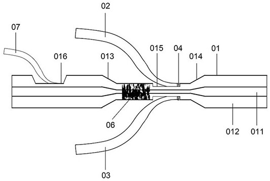
[0019] figure 1 The structure of the side-pump beam combiner used in the high-power fiber laser system provided by the embodiment of the present invention is shown, and only the parts related to the embodiment of the present invention are shown for convenience of description.

[0020] like figure 1 As shown, the side-pump beam combiner for high-power fiber laser systems provided in this embodiment includes a signal fiber 01, the signal fiber includes a core 011 and a cladding 012, and the middle part of the signal fiber is tapered to form A tapered area, the tapered area includes a flat area and a tapered area located at both ends of the flat area, in the figure, the two tapered areas are marked as 013 and 014, and the cladding part of the flat area is formed with a first A cladding corrosion zone 015, the side wall end surface of the first cladding corrosion zone 015 is bonded with a number of pumping fibers through the refractive index matching bonding solution 04, there ar...

Embodiment 2

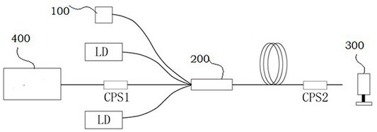
[0040] This embodiment provides an application scenario of the beam combiner, such as figure 2 As shown, the (2+1)×1 beam combiner 200 is used as a forward beam combiner for the fiber amplifier, the output fiber size of the seed source 400 is 20 / 400, and passes through a 20 / 400-30 / 400 mode field matcher (MFA ) into the beam combiner. The core-to-cladding ratio of the LD tail fiber of the amplified semiconductor laser is 200 / 220, which is consistent with the size of the pump fiber of the beam combiner. The pump light is coupled into the cladding of the active fiber through the beam combiner. A cladding light stripper is fused at the output end to filter the cladding laser to improve the beam quality. A power meter 300 is shown for measuring the output power of the entire device. The test system 100 has multiple uses: 1) a power meter is placed behind it to monitor the backward optical power; 2) a spectrometer can be used to observe nonlinear effects (mainly stimulated Brillo...


PUM

PropertyMeasurementUnit
diameteraaaaaaaaaa
diameteraaaaaaaaaa
lengthaaaaaaaaaa

Abstract

The present invention is applicable to the field of optical fiber devices, and provides a side-pump beam combiner for high-power optical fiber laser systems, including a signal optical fiber, the signal optical fiber includes a core and a cladding, and it is characterized in that the signal optical fiber The central tapering forms a tapered region, the tapered region includes a straight region and tapered regions located at both ends of the straight region, the cladding portion of the straight region is formed with a section of the first cladding corrosion region, the first A number of pumping optical fibers are bonded on the side wall end surface of the cladding corrosion zone through a refractive index matching adhesive liquid, and the straight zone located in front of the first cladding corrosion zone is a textured zone. The beam combiner recycles the pump light that is not coupled into the cladding, which improves the coupling efficiency and avoids heat accumulation and damage to the fiber; by tapering the signal fiber and then coupling the pump light to the side, it effectively filters out Some high-order modes reduce the stress sensitivity caused by high-order modes and optimize the beam quality.

Description

technical field [0001] The invention belongs to the field of optical fiber devices, in particular to a side-pump beam combiner used in a high-power optical fiber laser system. Background technique [0002] The fiber beam combiner is one of the core components of the fiber laser. The pump beam combiner is used to couple the pump light and the signal light into the active fiber to achieve laser amplification; the signal beam combiner is used to combine the laser beams to achieve Higher output power. There are mainly two types of fiber combiner implementation ideas: end-face coupling and side coupling. End-face coupling has high coupling efficiency by fusing the input fiber and output fiber end faces. It is the main method for making high-power beam combiners. However, end-face pumping also has disadvantages. On the one hand, because it involves end-face re-melting, it cannot Avoid introducing additional loss; on the other hand, because the size of the input fiber bundle shou...

Claims


Application Information

Patent Timeline
Patent Type & Authority Patents(China)
IPC IPC(8): H01S3/094H01S3/0941H01S3/067G02B6/02
CPCH01S3/094053H01S3/094019H01S3/0941H01S3/06708G02B6/02
Inventor 刘茵紫王勇兰根书
Owner 武汉聚合光子技术有限公司
Learn More