
Magnetic resonance coil assembly and control method of magnetic resonance equipment

A coil assembly and magnetic resonance technology, which is applied in the control field of magnetic resonance coil assemblies and magnetic resonance equipment, can solve the problems of inconvenient wearing and use, large volume of the coil body, and complicated positioning, so as to simplify the scanning process and improve the circuit The effect of increasing the degree of integration and improving the degree of flexibility

Pending Publication Date: 2021-12-21
SHANGHAI UNITED IMAGING HEALTHCARE
View PDF2 Cites 0 Cited by
  • Summary
  • Abstract
  • Description
  • Claims
  • Application Information

AI Technical Summary

Problems solved by technology

[0003] However, in traditional magnetic resonance coils, the circuit structures such as capacitors, inductors, and diodes are concentrated on the coil body, and a thick mechanical shell is placed in the EVA material to protect the circuit structure, resulting in a large volume and heavy weight of the coil body. High cost and difficult to produce
During the scanning process, when the coil body is fixed to the human body through straps, the positioning is complicated and the wearer's comfort is not good, which makes wearing and using both inconvenient

Method used


Image

  • Magnetic resonance coil assembly and control method of magnetic resonance equipment
  • Magnetic resonance coil assembly and control method of magnetic resonance equipment
  • Magnetic resonance coil assembly and control method of magnetic resonance equipment

Examples


Embodiment Construction

[0027] In order to facilitate the understanding of the present application, the present application will be described more fully below with reference to the relevant drawings. Embodiments of the application are given in the drawings. However, the present application can be embodied in many different forms and is not limited to the embodiments described herein. On the contrary, the purpose of providing these embodiments is to make the disclosure of this application more thorough and comprehensive.

[0028] Unless otherwise defined, all technical and scientific terms used herein have the same meaning as commonly understood by one of ordinary skill in the technical field to which this application belongs. The terms used herein in the specification of the application are only for the purpose of describing specific embodiments, and are not intended to limit the application.

[0029] It can be understood that the terms "first", "second" and the like used in this application may be...


PUM


Abstract

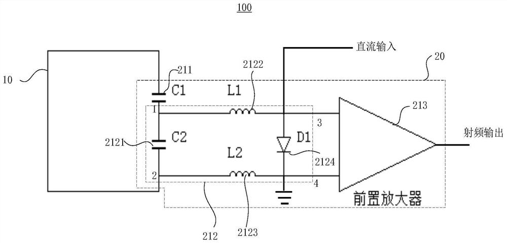
According to the magnetic resonance coil assembly and the control method of the magnetic resonance equipment, the working state of the coil body can be regulated and controlled by connecting the adjusting control circuit with the first connecting end and the second connecting end of the coil body. Therefore, the coil body is adjusted to be switched between the resonance state and the detuning state through the control signal input by the direct current input end. At the moment, the magnetic resonance signal can be regulated and controlled by the adjusting control circuit so as to output the radio frequency signal. Meanwhile, electronic devices for regulating and controlling the frequency, the detuning state, the impedance and the like of a resonance circuit where the coil body is located are integrated in the printed circuit board. The adjusting control circuit and the coil body are arranged independently, no patch type or distributed capacitor or other electronic devices exist in the coil body independently, the area of a front-end circuit of the coil body is reduced, the flexibility degree of the magnetic resonance radio frequency coil is improved, and the size and weight of the circuit are reduced.

Description

technical field [0001] The present application relates to the technical field of magnetic resonance equipment, in particular to a magnetic resonance coil assembly and a control method for the magnetic resonance equipment. Background technique [0002] The magnetic resonance system mainly includes magnets, gradient coils, radio frequency coils, and several subsystems of the receiving link. A uniform static magnetic field is generated by a superconducting magnet, and a magnetic resonance signal is generated by exciting the spin precession of hydrogen nuclei through a radio frequency transmitting coil, and the spatial information encoding of the signal is carried out by using a gradient coil. The above-mentioned magnetic resonance signals are collected by a radio frequency receiving coil, converted into digital signals through a receiving link, and finally reconstructed by a computer to obtain a magnetic resonance image. As an important part of the magnetic resonance system, t...

Claims


Application Information

Patent Timeline
IPC IPC(8): G01R33/36G01R33/34
CPCG01R33/3628G01R33/34084G01R33/34092G01R33/3415G01R33/3657G01R33/365G01R33/3621G01R33/3607H03F3/45475H03F2200/451H03F2203/45568H03F3/195H03F3/19
Inventor 王振车韶陆海范贤文李烨
Owner SHANGHAI UNITED IMAGING HEALTHCARE
Learn More