Machining device and method for sharpness of antenna target plate

The technology of a processing device and a processing method is applied in the field of processing devices for the sharpness of an antenna target plate, which can solve the problems of the antenna unable to stably receive and release microwave signals, the antenna unable to achieve stable signal transmission, and the increase of production costs, and to reduce mechanical strength. , The effect of stable transmission and reduction of production difficulty

Active Publication Date: 2022-01-04
四川英创力电子科技股份有限公司
View PDF3 Cites 3 Cited by
  • Summary
  • Abstract
  • Description
  • Claims
  • Application Information

AI Technical Summary

Problems solved by technology

However, there are some problems in this method. For example, the protrusions are tightly attached to the target board, which leads to the consumption of a large amount of etching solution to etch the protrusions in the subsequent etching process, thereby increasing the production cost; the sharpness of the processed antenna >20μm, the sharpness of the antenna will cause the antenna to be unable to stably retract the microwave signal, resulting in the antenna being unable to achieve stable transmission of the signal

Method used


Image

  • Machining device and method for sharpness of antenna target plate
  • Machining device and method for sharpness of antenna target plate
  • Machining device and method for sharpness of antenna target plate

Examples


Embodiment 1

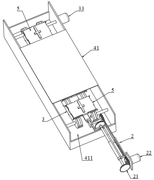
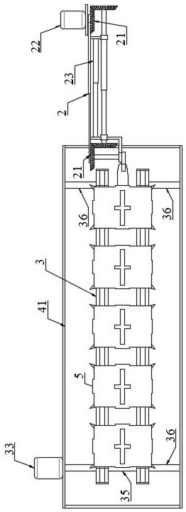
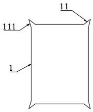
[0049] Such as figure 1 As shown, the present embodiment provides a processing device for the sharpness of the antenna target plate, such as image 3 As shown, the four corners of the target board 1 are PAD positions 11, and the PAD position 11 is provided with a protrusion 111, and the protrusion 111 is triangular, circular or square, and the processing device includes a target board transfer mechanism 2, a conveying mechanism 3, a sandblasting Mechanism 4 and protective shell 5.

[0050] Specifically, such as Figure 4As shown, the protective case 5 includes a target board bottom bracket 51 and a target board cover 52. The target board cover 52 is fastened to the target board bottom bracket 51. The inside of the protective case 5 is used to place the target board 1, and the target board bottom The four corners of holder 51 are provided with special-shaped convex plate 511, and the shape and size of special-shaped convex plate 511 are identical with protrusion 111, and prot...

Embodiment 2

[0060] Such as Figure 10 As shown, the present embodiment provides a method for processing the sharpness of the antenna target plate, using the processing device for the sharpness of the antenna target plate in Embodiment 1, the processing method includes the following steps:

[0061] S1. Place the target board 1 on the target board bottom support 51, the protrusion 111 is located on the special-shaped convex plate 511, and then fasten the target board cover 52 to the target board bottom support 51, and the protrusion 111 is exposed on the target board cover 52 outside;

[0062] S2. At this time, the guide column 231 and the telescopic rod 23 are all in a vertical state, and the clamping plate 24 is in a horizontal state;

[0063] Place the target board bottom bracket 51 on the clamping plate 24, match the slot 241 of the clamping plate 24 with one of the branches of the cross 53, use the first motor 22 to turn the steering plate 221 counterclockwise, and make the clamping p...


PUM


Abstract

The invention discloses a machining device and method for the sharpness of an antenna target plate. The machining device comprises a target plate transferring mechanism, a conveying mechanism, a sand blasting mechanism and a protective shell. The protective shell comprises a target plate bottom support and a target plate upper cover, the target plate upper cover is buckled on the target plate bottom support, and the protective shell is used for placing a target plate; the target plate transferring mechanism is used for transferring the protective shell to the conveying mechanism; the sand blasting mechanism comprises a sand blasting pool and a plurality of sand nozzles, and the sand nozzles are used for blasting sands to the target plate; and the conveying mechanism comprises two groups of conveying plates which are oppositely arranged, two conveying chains and a second motor, each group of conveying plates comprises an outer plate and an inner plate which are oppositely arranged, one conveying chain is located between the outer plate and the inner plate, and the conveying chains are used for placing the protective shell and enabling the protective shell to move from one end of the sand blasting mechanism to the other end of the sand blasting mechanism. By using the machining device and method disclosed by the invention, uniform sand blasting can be independently conducted on bulges, so that the mechanical strength of each bulge is weakened; and after etching treatment, an antenna with the sharpness smaller than 20 microns can be obtained.

Description

technical field [0001] The invention relates to the technical field of radar antenna processing, in particular to a processing device and method for sharpness of an antenna target plate. Background technique [0002] In order to ensure the stable transmission of signals by the antenna, it is necessary to control the sharpness of the antenna target board within an appropriate range. The method in the prior art is to process a triangular, circular or square shape on the four PAD positions of the target board by means of gain compensation. bump, and then the target board is subjected to copper reduction, copper deposition, exposure, electroplating, and etching. However, there are some problems in this method. For example, the protrusions are tightly attached to the target board, which leads to the consumption of a large amount of etching solution to etch the protrusions in the subsequent etching process, thereby increasing the production cost; the sharpness of the processed ant...

Claims


Application Information

Patent Timeline
Patent Type & Authority Applications(China)
IPC IPC(8): B24C1/00B24C3/12B24C9/00C23C28/00
CPCB24C1/00B24C3/083B24C3/12B24C9/00C23C28/00
Inventor 张仁军李清华林涛胡志强牟玉贵
Owner 四川英创力电子科技股份有限公司
Why Eureka
Try Eureka