
Prefabricated concrete subway station

A prefabricated assembly and concrete technology, applied in construction, artificial islands, excavation, etc., can solve the problems of large labor resources and raw materials consumption, large impact on road traffic, poor on-site operating environment, etc., to achieve fast construction speed, less wet work, The effect of reducing stacking

Active Publication Date: 2022-01-04
SHANDONG UNIV +3
View PDF10 Cites 0 Cited by
  • Summary
  • Abstract
  • Description
  • Claims
  • Application Information

AI Technical Summary

Problems solved by technology

[0002] Most subway stations are constructed by the open-cut method, which consumes a large amount of labor resources and raw materials. The construction site and material transportation have a great impact on road traffic, the degree of industrialization is low, the on-site operating environment is poor, and environmental pollution, noise pollution and other problems caused by construction increasingly serious

Method used


Image

  • Prefabricated concrete subway station
  • Prefabricated concrete subway station
  • Prefabricated concrete subway station

Examples


Embodiment 1

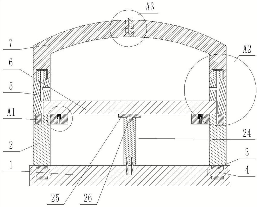
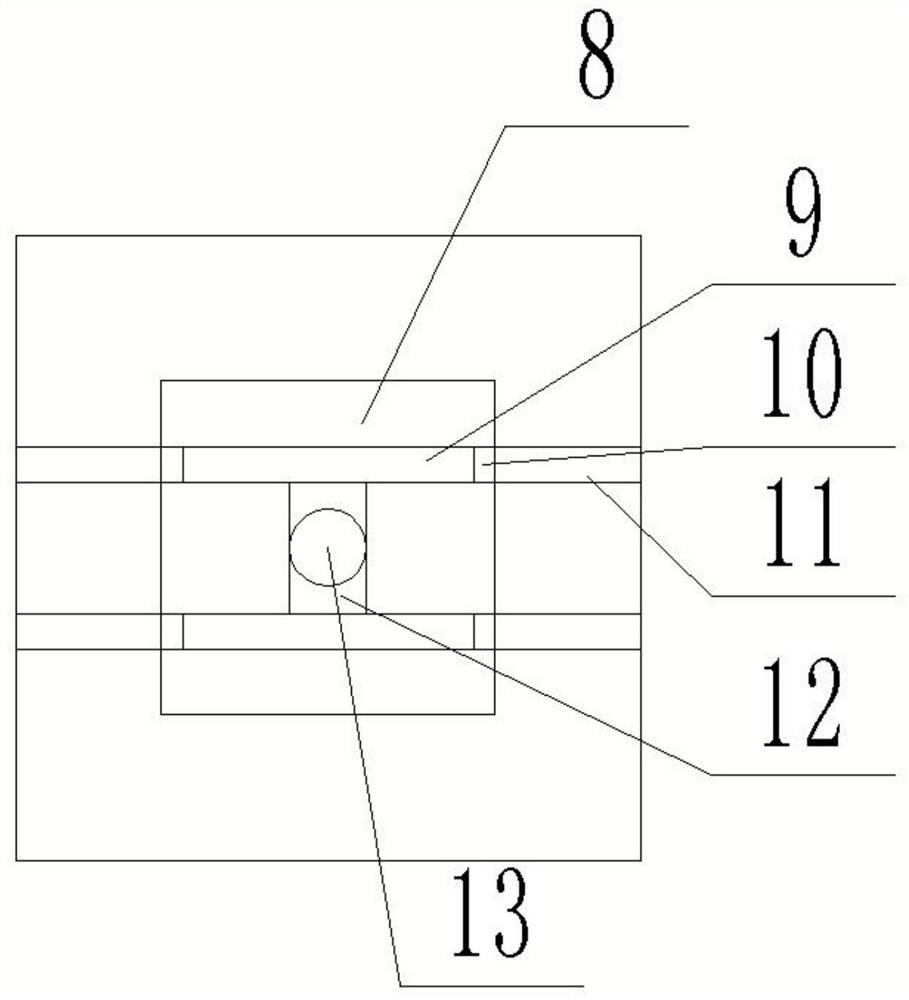
[0029] refer to Figure 1-6 , the present invention provides a prefabricated concrete subway station, which includes a plurality of assembly units spliced ​​in sequence, the assembly unit includes: a base plate 1, the base plate 1 is arranged in the foundation pit, and the two sides of the top surface of the base plate 1 are respectively provided with lower side plates 2, The bottom surface of the lower side plate 2 is fixedly connected with the plug-in block 3, and the two sides of the top surface of the base plate 1 are respectively provided with plug-in slots suitable for the plug-in block 3, and the two sides of the base plate 1 are respectively provided with plug-in holes. One end of the connecting column 4 is threadedly connected, and the other end of the connecting column 4 passes through the plug-in block 3 and is threadedly connected with the plug-in block 3. The top surface of the lower side plate 2 is provided with an upper side plate 5, which is connected to the low...

Embodiment 2

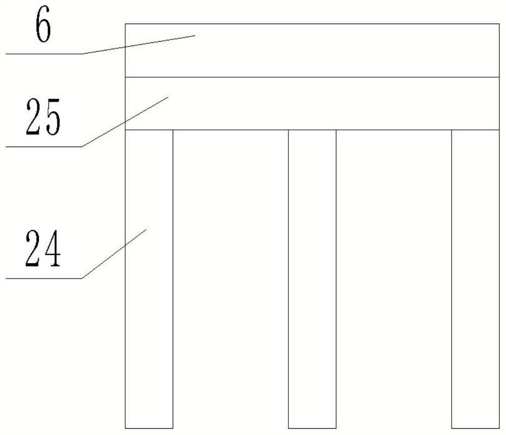
[0041] refer to Figure 7 , there is a cavity in the top plate 7, a steel bar frame 27 is arranged in the cavity, and the steel bar frame 27 is embedded on the inner wall of the cavity. Reduce the load on the upper side plate 5, the lower side plate 2 and the base plate 1, and at the same time make the construction handling and installation process easier and faster, and reduce the construction pressure.

Embodiment 3

[0043] refer to Figure 8 , the prefabricated panel 6 includes a first reinforcement layer 28 and a second reinforcement layer 29, the first reinforcement layer 28 and the second reinforcement layer 29 adopt reinforcement and wire mesh interlaced winding arrangement, between the first reinforcement layer 28 and the second reinforcement layer 29 A plurality of connecting steel columns 30 are affixed, the top of the connecting steel column 30 is affixed to the bottom of the first reinforcement layer 28, the bottom of the connection steel column 30 is affixed to the top surface of the second reinforcement layer 29, the first reinforcement layer 28 and the second reinforcement layer Concrete is poured in the reinforcing bar layer 29, a foam board 31 is arranged between the first reinforcing bar layer 28 and the second reinforcing bar layer 29, the first concrete layer 32 is fixed on the top surface of the first reinforcing bar layer 28, and the second reinforcing bar layer 29 is fi...


PUM


Abstract

The invention discloses a prefabricated concrete subway station. The prefabricated concrete subway station comprises a plurality of assembly units which are spliced in sequence, each assembly unit comprises a base plate, the base plate is arranged in a foundation pit, lower side plates are arranged on the two sides of the top face of the base plate correspondingly, inserting blocks are fixedly connected to the bottom faces of the lower side plates, inserting grooves matched with the inserting blocks are formed in the two sides of the top face of the base plate correspondingly, inserting holes are formed in the two side faces of the base plate correspondingly, one ends of connecting columns are connected into the inserting holes through threads, and the other ends of the connecting columns penetrate through the inserting blocks and are connected with the inserting blocks through threads. Upper side plates are arranged on the top faces of the lower side plates, prefabricated plates are arranged between the upper side plates and the lower side plates, positioning devices are correspondingly arranged on the two sides of the bottom faces of the prefabricated plates, the side faces of the positioning devices are fixedly connected with the tops of the side faces of the lower side plates, connecting devices are arranged in the upper side plates, top plates are correspondingly arranged on the top faces of the two upper side plates, a reinforcing device is arranged between the two opposite side faces of the two top plates, a supporting device is arranged in the center of the bottom faces of the prefabricated plates, and the bottom face of the supporting device is detachably connected with the top face of the base plate.

Description

technical field [0001] The invention relates to the technical field of subway stations, in particular to a prefabricated concrete subway station. Background technique [0002] Most subway stations are constructed by the open-cut method, which consumes a large amount of labor resources and raw materials. The construction site and material transportation have a great impact on road traffic, the degree of industrialization is low, the on-site operating environment is poor, and environmental pollution, noise pollution and other problems caused by construction getting worse. The prefabricated subway station can realize the standardization of design, prefabricated components and construction, which will greatly shorten the construction period of the subway station, reduce the area occupied by construction material stacking and processing, and reduce a large number of on-site operations such as concrete pouring, thereby saving labor and reducing construction waste , with green, en...

Claims


Application Information

Patent Timeline
Patent Type & Authority Applications(China)
IPC IPC(8): E02D29/045E02D29/00E02D17/02E02D15/02E02D29/16
CPCE02D29/045E02D29/04E02D17/02E02D15/02E02D29/16
Inventor 郭相武龚斯昆姜晓明胡学龙胡云飞黄鹏王光伟王夏冰徐祥云张真煌刘薇何俊王跃王培军刘芳州
Owner SHANDONG UNIV
Features
  • Generate Ideas
  • Intellectual Property
  • Life Sciences
  • Materials
  • Tech Scout
  • Unparalleled Data Quality
  • Higher Quality Content
  • 60% Fewer Hallucinations
Learn More