Method for improving oil well productivity through nano system composite CO2 huff and puff

A technology for CO2 and oil wells, applied in wellbore/well components, chemical instruments and methods, and production fluids, etc., can solve the problems of reducing permeability, achieve the effects of reducing permeability, replenishing formation energy, and avoiding deposition

Pending Publication Date: 2022-01-04
CHINA PETROLEUM & CHEM CORP +1
View PDF10 Cites 1 Cited by
  • Summary
  • Abstract
  • Description
  • Claims
  • Application Information

AI Technical Summary

Problems solved by technology

[0006] Existing CO 2 The composite huff and puff method can effectively improve the single well productivity of oil wells, but in CO 2 In the process of "spit", the light components in crude oil are easily recovered from the reservoir, while the heavy components such as asphaltene in crude oil will be adsorbed on the rock surface, making the rock oil-wet, thereby reducing the permeability

Method used


Image

  • Method for improving oil well productivity through nano system composite CO2 huff and puff
  • Method for improving oil well productivity through nano system composite CO2 huff and puff
  • Method for improving oil well productivity through nano system composite CO2 huff and puff

Examples


Embodiment 1

[0039] Well P8 in an oilfield, the effective thickness of the oil layer is 7.1m, the average porosity is 25.4%, and the average permeability is 16×10 -3 μm 2 , the reservoir temperature is 50°C, the reservoir pressure is 10.41MPa, and the surface crude oil density is 0.9319t / m 3 , ground crude oil viscosity 765.52mPa.s, freezing point 39 ℃.

[0040] Nano solution injection amount Q is: V=3.14R 2 Hфβ=3.14×7.1 2 ×10×0.254×0.8=558m 3 , where: R takes a value of 10, and β takes a value of 0.8. Calculation of liquid CO according to the gas-liquid ratio of 2:1 2 The injection volume is 1116t.

[0041] Construction steps:

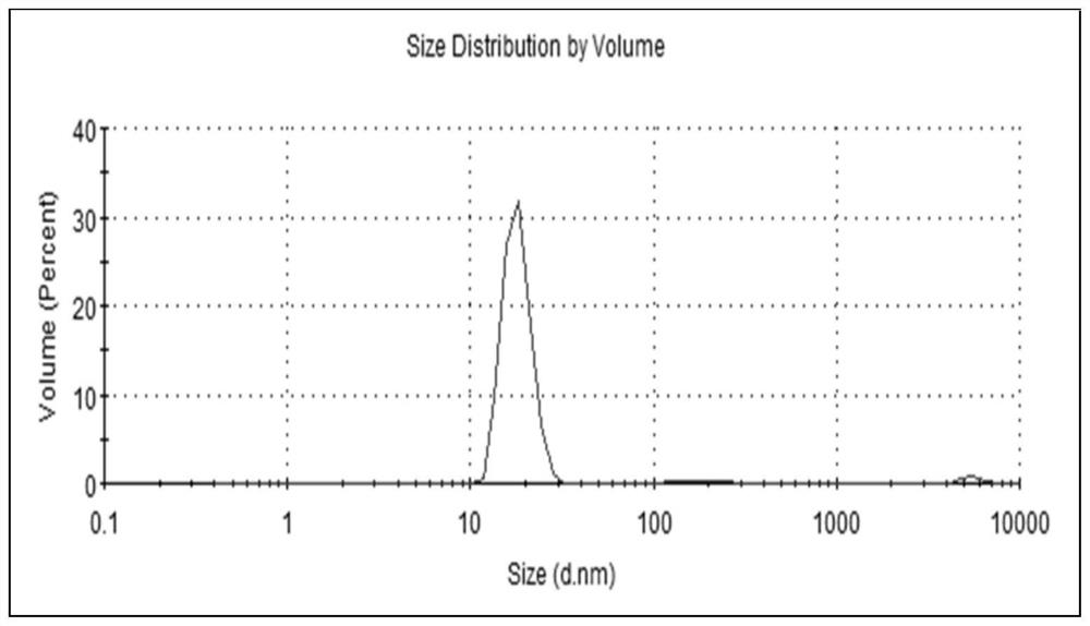
[0042] (1) The solid content of the prepared nanoparticles is 0.005% water-based nano-solution: the water-based nano-solution is composed of the following components according to the mass percentage: 0.005% nano-SiO 2 Particles, 3% fluorine-containing silicone (perfluorosiloxane with a methoxy end group and a carbon chain length of 6), 0.3% fluorocarbon su...

Embodiment 2

[0052] Well P11 in an oilfield, the oil layer has an effective thickness of 4.8m, an average porosity of 24.3%, and an average permeability of 27×10 -3 μm 2 , the reservoir temperature is 50°C, the reservoir pressure is 10.41MPa, the surface crude oil density is 0.9457t / m3, the surface crude oil viscosity is 896.62mPa.s, and the freezing point is 40°C.

[0053] Nano solution injection amount Q is: V=3.14R 2 Hфβ=3.14×4.8 2 ×20×0.243×0.8=281m 3 , where: R takes a value of 20, and β takes a value of 0.8. Calculation of liquid CO according to the gas-liquid ratio of 2:1 2 The injection volume is 563t.

[0054] Construction steps:

[0055] (1) Prepare the water-based nanometer solution with embodiment 1.

[0056] (2) Use a pump truck to inject the water-based nano-solution into the formation through the oil jacket annulus, with an injection displacement of 40m 3 / d, use the method of day injection and night stop, so that the nano solution can fully interact with the formati...


PUM

PropertyMeasurementUnit
particle diameteraaaaaaaaaa
particle sizeaaaaaaaaaa
thicknessaaaaaaaaaa

Abstract

The invention discloses a method for improving oil well productivity through nano system composite CO2 huff and puff. The method comprises the following steps of (1) injecting a nano solution slug: preparing a water-based nano solution with the solid content of 0.005-0.01%, and injecting the water-based nano solution into a stratum from an oil well oil jacket annulus; (2) injecting a liquid CO2 slug: injecting the liquid CO2 slug into a stratum from the oil well oil jacket annulus, wherein the mass ratio of the injected CO2 to the water-based nano solution is (1.5-2.2): 1; and (3) stopping injection and soaking the well, specifically, after injection of the liquid CO2 is completed, closing the well for soaking, and the soaking time is 10-20 days. According to the method, nano-particles can be adsorbed on the surface of rock, the lipophilicity of the nano-particles is changed into lipophobicity, the deposition of asphaltene is effectively prevented, the damage of asphaltene precipitation to a reservoir in the CO2 spitting process is greatly reduced, and the fluidity of crude oil is improved.

Description

technical field [0001] The invention relates to the field of oil well stimulation in the process of oil field development, in particular to a nano system composite CO 2 Huff and puff methods to increase well productivity. Background technique [0002] Low-permeability reservoirs have the characteristics of low porosity, low permeability, low natural productivity, and no production without water injection. To solve the development problems of low-permeability oilfields, carbon dioxide huff and puff has become an effective production stimulation technology for low-permeability reservoirs. Carbon dioxide huff and puff oil recovery technology is to inject a certain amount of carbon dioxide into the oil layer under a certain pressure. After a period of time, the viscosity of the crude oil can be significantly reduced, the volume of the crude oil can be expanded, the relative permeability of the oil phase can be increased, and the production of the oil well can be increased. [0...

Claims


Application Information

Patent Timeline
Patent Type & Authority Applications(China)
IPC IPC(8): E21B43/22E21B43/16C09K8/594
CPCE21B43/16E21B43/164C09K8/594
Inventor 宋奇时维才纪艳娟马惠康玉阳
Owner CHINA PETROLEUM & CHEM CORP
Why Eureka
Try Eureka