
Flushing system and flushing method for secondary circuit of high-temperature gas cooled reactor

A high-temperature gas-cooled reactor and flushing system technology, applied in the field of nuclear power, can solve the problems of increasing the difficulty of flushing wastewater control and processing costs, and achieve the effects of flexible flushing control methods, reduced wastewater discharge, and improved flushing effects

Active Publication Date: 2022-01-04
HUANENG SHANDONG SHIDAO BAY NUCLEAR POWER CO LTD +1
View PDF4 Cites 0 Cited by
  • Summary
  • Abstract
  • Description
  • Claims
  • Application Information

AI Technical Summary

Problems solved by technology

The thermal flushing of the secondary circuit of the high-temperature reactor can only be carried out after the reactor is critical, with "nuclear" flushing, which greatly increases the difficulty of controlling the flushing wastewater and the treatment cost

Method used


Image

  • Flushing system and flushing method for secondary circuit of high-temperature gas cooled reactor

Examples


Embodiment 1

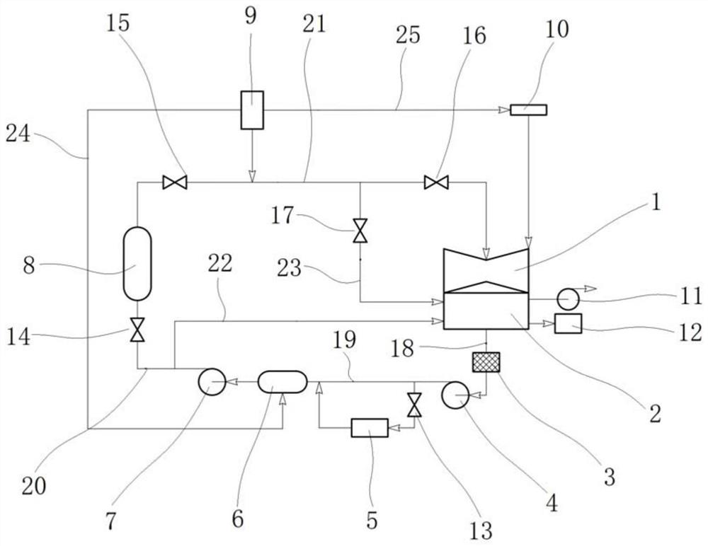
[0046] This embodiment provides a specific implementation of the high temperature gas-cooled reactor secondary loop flushing system, such as figure 1 As shown, the flushing system includes a steam turbine 1 , a condenser 2 , a condensate pump 4 , a deaerator 6 , a feed water pump 7 and a steam generator 8 . The steam turbine 1 communicates with the condenser 2, the condenser 2 communicates with the condensate pump 4 through a first pipeline 18, and the condensate pump 4 communicates with the deaerator through a second pipeline 19 6, the deaerator 6 communicates with the feedwater pump 7 through a pipeline, the feedwater pump 7 communicates with the steam generator 8 through a third pipeline 20, and the steam generator 8 communicates with the steam generator 8 through a fourth pipeline The road 21 communicates with the steam turbine 1 . The fifth pipeline 22 is connected between the third pipeline 20 and the condenser 2, and the fifth pipeline 22 is connected to the position n...

Embodiment 2

[0054] This embodiment provides a specific implementation of the flushing method, using the flushing system in Example 1, comprising the following steps: closing the fourth valve 13 to isolate the finishing device 5, closing the first valve 14, and the second valve 15 to isolate Steam generator 8, close the third valve 16 to isolate the steam turbine 1, open the steam trap 17; start the condensate pump 4, so that the condensate in the condenser 2 passes through the first pipeline 18 and the second pipeline 19 to the deaerator 6 , and then start the feed water pump 7 to return the feed water in the deaerator 6 to the condenser 2 through part of the third pipeline 20 and the fifth pipeline 22, so as to realize the cold cycle flushing of the secondary circuit water system; start the electric boiler 9, Part of the steam generated by the electric boiler 9 enters the condenser 2 through the steam trap 17, and performs hot flushing on the fourth pipe. At the same time, the steam heats...


PUM


Abstract

The invention provides a flushing system and a flushing method for a secondary circuit of a high-temperature gas cooled reactor, and belongs to the technical field of nuclear power. The flushing system includes: a steam turbine; a condenser; a condensate pump; a fine treatment device; a deaerator; a feed pump; an electric boiler; a shaft seal; a vacuumizing device; a steam generator; a filter screen; and valves and pipelines. When the steam generator is isolated, condensate water passes through the deaerator and then the feed pump and returns to the condenser to carry out secondary loop cold-state circulating flushing. Meanwhile, the electric boiler is started, a steam pipeline is subjected to hot-state flushing, water in the condenser is heated to improve the flushing effect of the condensate water, supplied water is heated through the temperature rise of the deaerator, and secondary loop hot-state circulating flushing is achieved. The fine treatment device can be put into use to rapidly improve the water quality, so that the water inlet requirement of the steam generator is met, and the washing period of a whole unit is shortened.

Description

technical field [0001] The invention relates to the technical field of nuclear power, in particular to a high-temperature gas-cooled reactor secondary circuit flushing system and a flushing method. Background technique [0002] The water quality of the secondary circuit is an important control index of the nuclear power plant, and the secondary circuit needs to be flushed at the initial stage of unit start-up to meet the requirements of the operating water quality. The traditional PWR secondary loop flushing method is to perform cold flushing first, and then heat the primary loop main pump to perform hot flushing. The high-temperature gas-cooled reactor steam generator is a direct-flow coil type, without online sewage discharge function, and the material is different from the pressurized water reactor steam generator, which requires extremely high water quality in the secondary circuit. In the initial stage of start-up, nitrogen filling maintenance is carried out in isolati...

Claims


Application Information

Patent Timeline
Patent Type & Authority Applications(China)
IPC IPC(8): G21D1/02B08B9/032
CPCG21D1/02B08B9/0321B08B2209/032Y02E30/00
Inventor 洪雨佳叶林赵峰马喜强黄鹏李振宇文发龙王锐崔鹏王磊
Owner HUANENG SHANDONG SHIDAO BAY NUCLEAR POWER CO LTD
Learn More