Ceramic milling cutter suitable for rough machining

A milling cutter and ceramic technology, which is applied in the field of ceramic cutters for rough machining of nickel-based superalloys, can solve problems such as groove wear and bond wear

Pending Publication Date: 2022-01-07
XIANGTAN UNIV
View PDF5 Cites 0 Cited by
  • Summary
  • Abstract
  • Description
  • Claims
  • Application Information

AI Technical Summary

Problems solved by technology

[0006] In view of the above problems, the present invention provides an integral ceramic milling cutter to solve the probl...

Method used


Image

  • Ceramic milling cutter suitable for rough machining
  • Ceramic milling cutter suitable for rough machining
  • Ceramic milling cutter suitable for rough machining

Examples


Embodiment Construction

[0023] Nickel-based high-temperature alloys have extremely high strength and hardness. When the cutting speed is only 30-60m / min, the processing efficiency of cemented carbide tools is extremely low. When the cutting speed increases, the cutting temperature will also increase sharply. When the cutting temperature reaches 800°C, the surface of the nickel-based superalloy workpiece will have a thermal softening effect, and the strength and hardness of the workpiece material will be greatly reduced. The loss of cobalt in the binder phase in the tool will increase the bonding wear of the tool, resulting in sharp wear of the tool, a significant decrease in life, and even an instantaneous failure of the tool that cannot be used.

[0024] The present invention is a ceramic milling cutter suitable for rough machining, which aims to replace the currently widely used cemented carbide cutter and ceramic cutter by changing the structure of the common integral ceramic milling cutter, and th...


PUM

PropertyMeasurementUnit
Diameteraaaaaaaaaa
Radiusaaaaaaaaaa
Angle angleaaaaaaaaaa

Abstract

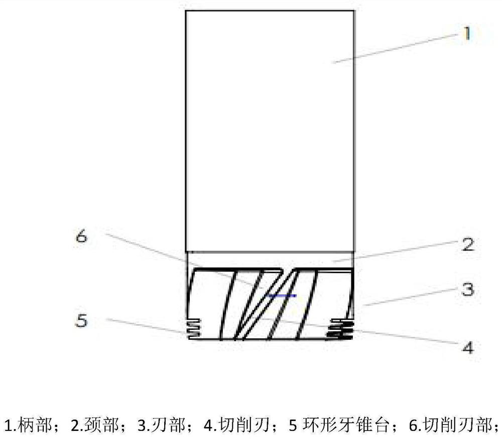
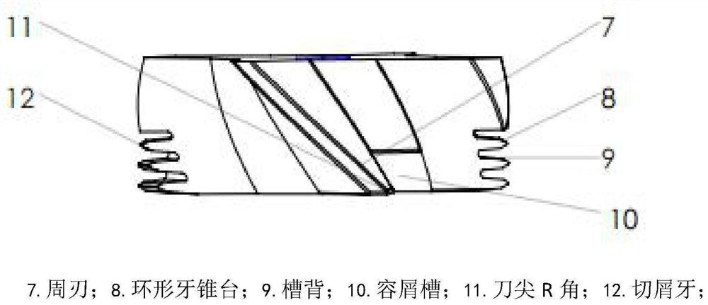
The invention relates to a ceramic milling cutter suitable for rough machining. The milling cutter is made of AL2O3/TiB2 metal ceramic materials and is mainly composed of a handle part, a neck part and a cutting edge part, the front end of the handle part is connected with the rear end of the neck part, the front end of the neck part is connected with the rear end of the cutting edge part, the handle part is used for installing the cutter and a cutter handle, the neck part is used for avoiding interference during cutting of the milling cutter, and the cutting edge part is a part, actually participating in cutting of a nickel-based high-temperature alloy workpiece, of the milling cutter. The cutting edge part is divided into two parts, the first part is a spiral cutting edge part which comprises a cutting edge and chip containing grooves, the cutting edge is composed of circumferential edges, end edges and tool nose R angles connecting the circumferential edges and the end edges, the tool nose R angles are used for connecting the circumferential edges and the end edges at the corresponding positions, and the two end edges are evenly distributed in the radial direction relative to the center of the front end face of the cutting edge part. Each end edge corresponds to one tool nose R angle and one circumferential edge, the circumferential edges are spirally arranged on the outer circumferential ring face of the cutting edge part at intervals, and the chip containing grooves are spirally arranged on the inner circumferential ring face of the cutting edge part at intervals (located behind an annular tooth frustum part and in front of the cutting edge part). The second part is the annular tooth frustum, at least three blades are arranged on the circumferential surface of the blade part, and a chip discharging groove is formed between every two adjacent blades. The blades are composed of cutting teeth which are arranged at equal intervals in the axial direction.

Description

technical field [0001] The invention belongs to the intersecting field of aerospace engineering and mechanical processing engineering, relates to the processing field of nickel-based high-temperature alloys, and in particular relates to a ceramic cutter for rough machining the nickel-based high-temperature alloys. Background technique [0002] With the wide application of nickel-based superalloys in nuclear power, petrochemical, aerospace and other fields, the research on the processing technology of nickel-based superalloys is also increasing. Nickel-based superalloys have excellent properties such as heat resistance, corrosion resistance, ductility resistance, creep resistance, and fatigue resistance, but they also have very strict requirements on processing technology. Nickel-based superalloys mainly have problems such as chip breakage, high cutting temperature, and severe tool wear during the cutting process, making high-speed steel tools and general carbide tools unable...

Claims


Application Information

Patent Timeline
IPC IPC(8): B23C5/02B23C5/18
CPCB23C5/18B23C5/02
Inventor 宋铁军王鹤鑫周正雷宾
Owner XIANGTAN UNIV
Why Eureka
Try Eureka