Shield tunneling machine

A technology of shield machine and main engine, which is applied in safety devices, mining equipment, earthwork drilling and mining, etc. It can solve the problems of stubborn impurities stuck in the slot knife gap and dust flying, so as to avoid blockage, reduce wear and save consumption Effect

Pending Publication Date: 2022-01-07
朱国庆
View PDF0 Cites 0 Cited by
  • Summary
  • Abstract
  • Description
  • Claims
  • Application Information

AI Technical Summary

Problems solved by technology

[0005] In view of the problems existing in the prior art, the purpose of the present invention is to provide a shield machine, which can solve the problem of stubborn impurities stuck in the gap between the groove knives and the problem of flying dust, and the equipment can save the consumption of power resources , has the characteristics of energy saving and emission reduction. In addition, it has the crushing pretreatment work before the transportation of soil residue, which is convenient for the transportation of the transporter.

Method used


Image

  • Shield tunneling machine
  • Shield tunneling machine
  • Shield tunneling machine

Examples


Embodiment 1

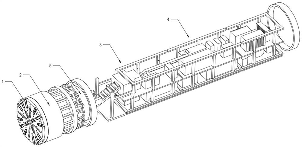
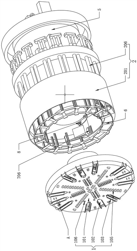
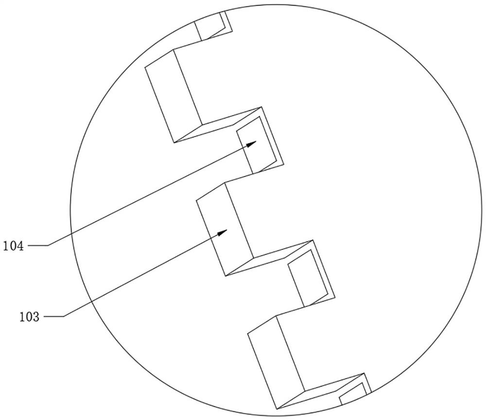
[0040] see Figure 1-7 , a shield machine, including a cutter head 1 and a host structure 2;

[0041] refer to figure 2 , the cutter head 1 is fixedly assembled at one end of the host structure 2, the inner wall of the host structure 2 close to the cutter head 1 is fixedly assembled with an internal structure 6, and the bottom of the inner wall of the host structure 2 near the cutter head 1 is fixedly provided with a crushing mechanism 7, The inner wall of the host structure 2 is located above the crushing mechanism 7 and is fixedly assembled with a water mist dust removal assembly 8. The host structure 2 is used to control the rotation of the cutter head 1 to complete the work of excavating the tunnel. Component 8 is then used to realize the work of dedusting.

[0042] refer to figure 1 , the host structure 2 is fixedly installed with a transporter 9 inside, the end of the host structure 2 facing away from the cutter head 1 is fixedly assembled with a segment mounting mac...

Embodiment 2

[0050] see Figure 6 and Figure 8 , a shield machine, including a cutter head 1 and a host structure 2;

[0051] refer to Figure 6 The crushing mechanism 7 also includes a rockfall chamber 701, which is fixedly arranged at the bottom end of the outer wall of the support pipe 201. Both sides of the rockfall chamber 701 are slidably assembled with sliding channel steel 703, and the inside of the sliding channel steel 703 is equidistantly fixed with guide rails The movable teeth 704, the opposite ends of the two driven teeth 704 are located inside the rockfall chamber 701 and are fixedly welded with crushing rakes 706. During the excavation process, soil residue enters the inner side of the disc body 101 after passing through the through hole 102. Finally, it automatically falls into the rockfall chamber 701 .

[0052] refer to Figure 8 , both sides of the inner bottom of the support tube 201 are fixedly installed with three-phase motors, and the output shafts of the three...

Embodiment 3

[0055] see Figure 9-10 , a shield machine, including a cutter head 1 and a host structure 2;

[0056] refer to Figure 10 , the water mist dedusting assembly 8 also includes a water injector 801, the two water injectors 801 are fixedly installed on the upper surface of the rockfall chamber 701, and are fixedly connected with the inner wall of the support pipe 201, and a driving wheel 802 is installed on the side wall of the water injector 801 for rotation , and the drive wheels 802 are all embedded in the grooves provided on the outer surface of the ring groove frame 208, the water injector 801 is rotatably installed with a crankshaft 808 fixedly connected with the drive wheel 802, and the end of the crankshaft 808 is rotatably equipped with a deflection rod 809, and the deflection rod 809 The end is rotatably connected with a piston 810, and the other side of the water injector 801 is fixedly connected with a water outlet pipe 803 and a water suction pipe 806 on both sides ...


PUM


Abstract

The invention discloses a shield tunneling machine, and belongs to the field of tunneling machine equipment. The shield tunneling machine comprises a cutterhead and a main machine structure, the cutterhead is fixedly assembled at one end of the main machine structure, an inner fixing frame is fixedly assembled on the inner wall of the side, close to the cutterhead, of the main machine structure, a crushing mechanism is fixedly arranged at the bottom of the inner wall of the side, close to the cutterhead, of the main machine structure, a water mist dust removal assembly is fixedly assembled on the portion, located above the crushing mechanism, of the inner wall of the main machine structure, a conveyor is fixedly installed in the main machine structure in a penetrating mode, and a pipe piece installing machine is fixedly assembled at the end, facing away from the cutterhead, of the main machine structure. The problems that stubborn impurities are clamped in gaps of groove cutters and dust flies can be solved, the equipment can save consumption of electric power resources, and has the characteristics of saving energy and reducing emission, in addition, the shield tunneling machine has the functions of crushing pretreatment before soil residue transportation, and transportation of a transporter is facilitated.

Description

technical field [0001] The invention relates to the field of boring machine equipment, more specifically, to a shield machine. Background technique [0002] The shield machine is a tunnel boring machine that uses the shield method. The construction method of the shield tunnel is that the tunnel boring machine builds (lays) the "shield" (referring to the supporting segment) of the tunnel while digging, which is different from the open construction. According to the working principle, the shield machine is generally divided into hand-excavated shield, extrusion shield, semi-mechanical shield (local air pressure, global air pressure), mechanical shield (open chest cutting shield, air pressure shield, slurry pressurized shield, earth pressure balance shield, hybrid shield, shaped shield); [0003] However, the existing shield machine has the following defects: in the excavation work of the existing shield machine, the particles with higher hardness in the soil will be stuck in ...

Claims


Application Information

Patent Timeline
IPC IPC(8): E21D9/08E21D9/12E21F5/04
CPCE21D9/08E21D9/12E21F5/04
Inventor 朱国庆
Owner 朱国庆
Why Eureka
Try Eureka