
Bipolar implantable myoelectric electrode assembly for stimulation and recording and application method thereof

An electrode assembly and implantable technology, applied in application, diagnostic recording/measurement, medical science, etc., can solve problems such as inability to record muscle electromyographic signals, injury of experimental animals, and complicated operation process, so as to reduce the difficulty of collection and improve The effect of controlling precision and ability and simplifying the process

Pending Publication Date: 2022-01-11
ACADEMY OF MILITARY MEDICAL SCI
View PDF4 Cites 0 Cited by
  • Summary
  • Abstract
  • Description
  • Claims
  • Application Information

AI Technical Summary

Problems solved by technology

Domestic research on implantable EMG electrodes is less, mainly focusing on the development of EMG acquisition devices such as EMG needles, microneedle electrodes, and Cuff electrodes, which are mostly used for clinical use, and there are few chronic implantable electrodes for animals. There are some implanted EMG electrodes used in animals in foreign countries, but the technology is blocked, the price is high, and there are electrodes shifting and falling off during use.
[0003] In summary, most EMG studies use surface EMG signals, which cannot record specific muscle EMG signals, and there are challenges in signal stability such as motion artifacts, skin impedance changes, and electrode displacement.
For implantable EMG electrodes, needle electrodes are the main ones. Not only is the operation process complicated, professional researchers are required to perform positioning and operation, and it will cause certain damage to experimental animals in a state of motion.

Method used


Image

  • Bipolar implantable myoelectric electrode assembly for stimulation and recording and application method thereof
  • Bipolar implantable myoelectric electrode assembly for stimulation and recording and application method thereof
  • Bipolar implantable myoelectric electrode assembly for stimulation and recording and application method thereof

Examples


Embodiment 1

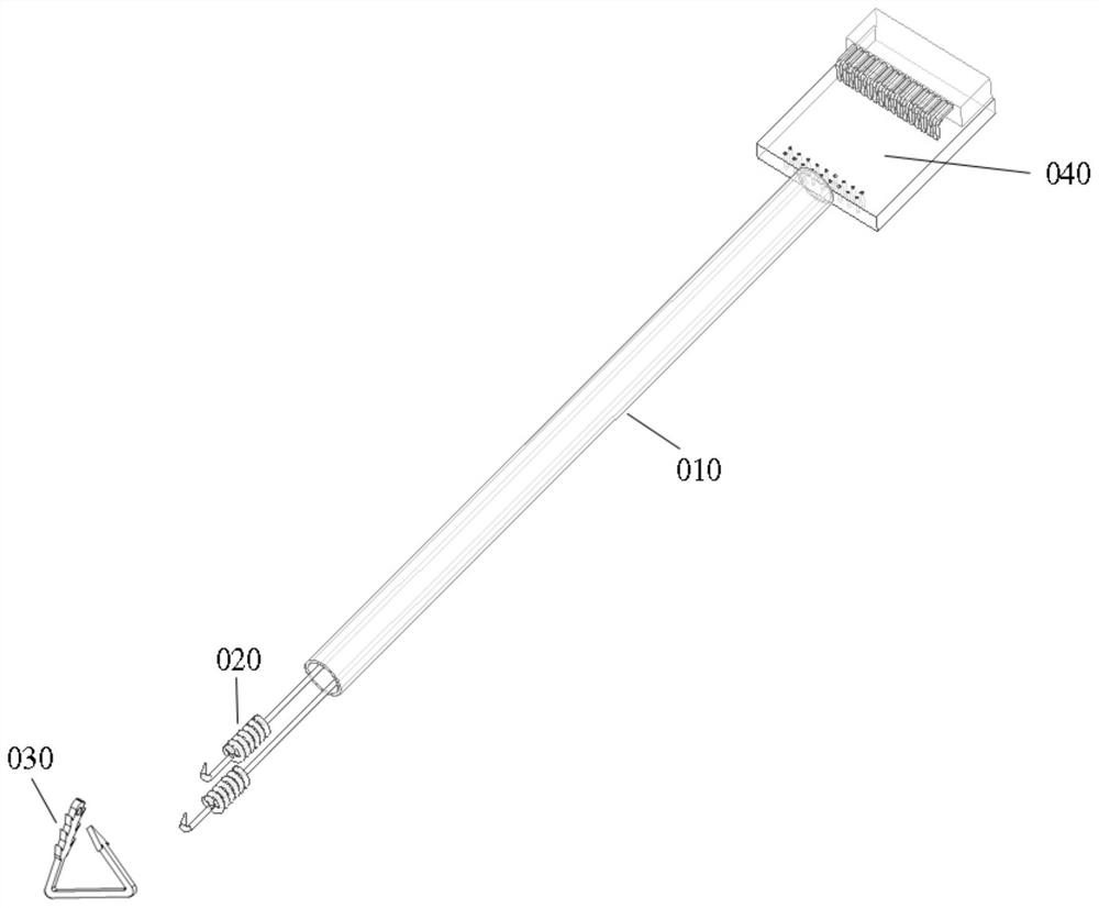
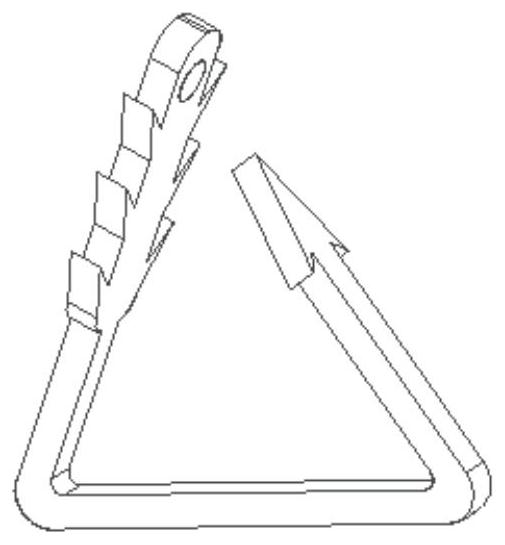
[0021] An implantable myoelectric electrode for stimulation and recording includes an electrode catheter 010, an electrode site 020 for stimulation and recording, an electrode interface 040 for connecting with a myoelectric recording system and an auxiliary Fixing jig 030 for electrode positioning.

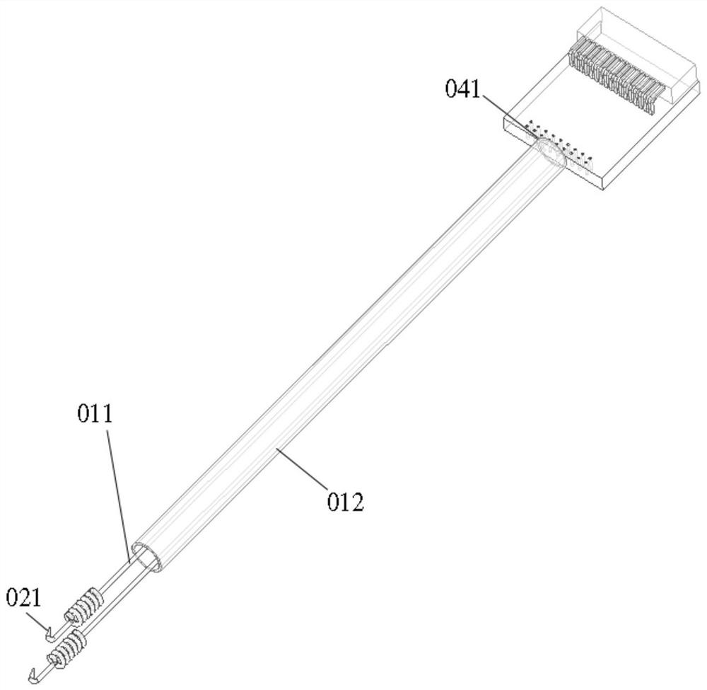
[0022] Such as Figure 1-2 As shown, the electrode catheter 010 is composed of an electrode wire 011 and a protective sleeve 012. The material of the electrode wire is 316 stainless steel or platinum-iridium alloy, etc., with a diameter of 0.3mm, and an insulating coating is attached to the outside of the electrode wire; the protective sleeve 012 is made of It is a fluorinated ethylene propylene copolymer. Two electrode wires 011 are placed in a protective sleeve, and the electrode wire 011 is placed in a protective sleeve 012 for packaging to prevent the inflow of liquid in the tissue. The insulating coating is removed from the end of the electrode wire 011 to record muscle. The...


PUM


Abstract

The invention discloses a bipolar implantable myoelectric electrode assembly for stimulation and recording and an application method thereof. The myoelectric electrode assembly comprises an electrode catheter, an electrode wire used for stimulating and recording sites, an electrode interface used for being connected with a myoelectric recording system and a fixing clamp used for assisting in positioning of the electrode assembly. The electrode catheter comprises the electrode wire and a protective sleeve that is attached to the outer side of the electrode wire. The electrode interface is located at the head end of the electrode assembly, and the fixing clamp is located at the tail end of the electrode assembly, so that the position of the electrode is relatively stable in the body. The implantable myoelectric electrode is an integral component. The implantable myoelectric electrode is simple in structure, easy to implant into subcutaneous muscular tissues, less in animal trauma and low in production cost. The implantable myoelectric electrode is expected to reduce the collection difficulty of electrode implantation in primate animals and improve the collection precision of electromyographic signals.

Description

technical field [0001] The invention belongs to the technical field of experimental zoology testing and animal experiment equipment, and in particular relates to a bipolar implantable myoelectric electrode assembly for stimulation and recording. Background technique [0002] One of the focuses in the field of brain-computer interface research is to accurately decode motion-related information, such as position, force, velocity, and acceleration, from the neuron activity of behavioral animals, and convert it into external information for controlling prosthetics, wheelchairs, and robotic arms. Device control instructions. In order to explore the neural coding mechanism and improve the control accuracy of the brain-computer interface system, when multimodal neural decoding based on non-human primates, it is necessary to collect the neural signals, eye movement signals, and myoelectric signals of non-human primates Signals and other multimodal electrophysiological signals. How...

Claims


Application Information

Patent Timeline
Patent Type & Authority Applications(China)
IPC IPC(8): A61B5/296A61B5/294
CPCA61B5/296A61B5/294A61B2503/40A61B2503/42
Inventor 周瑾刘冀王常勇王保增李斯伟
Owner ACADEMY OF MILITARY MEDICAL SCI
Learn More