Low-energy-consumption sewage deep denitrification system
A deep denitrification and low energy consumption technology, applied in biological water/sewage treatment, water/sludge/sewage treatment, water pollutants, etc., can solve problems such as low treatment capacity, incomplete nitrogen removal, and increased energy consumption. To achieve the effect of improving the efficiency of denitrification treatment, reducing secondary pollution, and improving denitrification treatment
- Summary
- Abstract
- Description
- Claims
- Application Information
AI Technical Summary
Problems solved by technology
Method used
Image
Examples
Embodiment 1
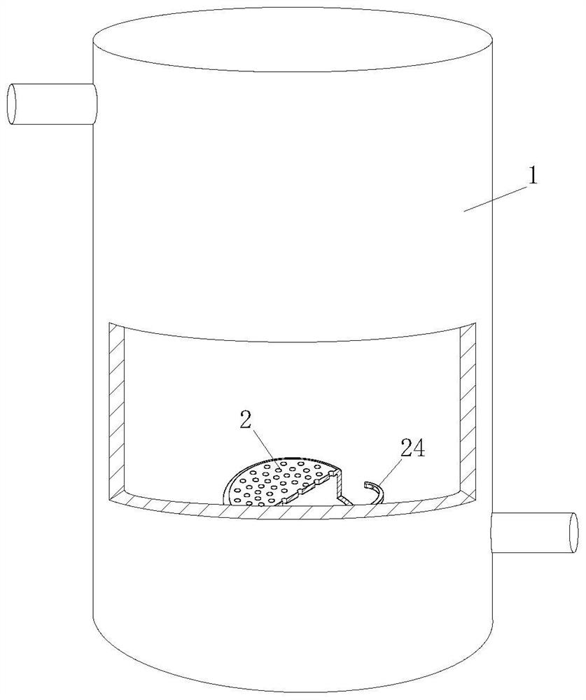
[0038] A low-energy sewage deep denitrification system, as follows Figure 1-4 As shown, it includes reaction device 1, water inlet device, water outlet device and air pump for sewage denitrification reaction, and also includes:
[0039] A biofilm carrier, the biofilm carrier is arranged in the reaction device, and the biofilm carrier is used for the habitat, growth and reproduction of microorganisms;
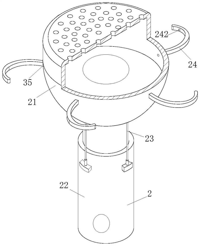
[0040] Aeration module 2, the aeration module 2 is connected with the air pump, the aeration module 2 is composed of an aeration head 21, an aeration pipe 22 and an adjustment unit 23, and the aeration head 21 is connected to the aeration unit through a ball joint The end of the pipe 22, and one or more sets of intake passages are opened on the ball joint, the adjustment unit 23 includes one or more of the cylinder or electric push rod, and one end of the adjustment unit 23 is installed on the aeration tube On the outer ring of 22, the other end is installed on the bottom of t...
Embodiment 2
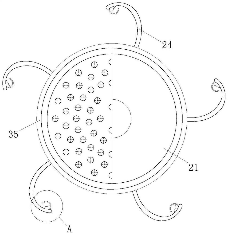
[0046] The difference from Embodiment 1 is as follows Figure 1-4 As shown, the end of the aeration tube 22 is connected with a driving source, and the driving source is one or more of a motor or a rotary cylinder. The driving source is used to drive the aeration tube 22 to rotate, and the outer ring of the aeration tube 22 A swivel is sleeved, and a through air inlet 221 is opened between the swivel and the aeration pipe 22, and the air inlet 221 communicates with the air pump through a hose;
[0047] The outer ring of the aeration head 21 is evenly provided with arc-shaped blades 24 , the arc-shaped blades 24 are bent toward the side close to the aeration head 21 , and the thickness of the middle part of the arc-shaped blades 24 gradually decreases toward both sides.
[0048] The driving source drives the aeration tube 22 to rotate, so that the aeration head 21 rotates, so that when the gas bursts through the aeration head 21, a vortex can be formed, so that the large bubble...
Embodiment 3
[0053] The difference from the second embodiment is as follows Figure 4 and Figure 6 As shown, the inside of the curved blade 24 is provided with an air channel one 241, one end of the air channel one 241 communicates with the inside of the aerator head 21, and the other end communicates with the opening 242 provided on the arc blade 24, the opening 242 is located at the end of the arc blade 24 away from the aeration head 21 .
[0054] By setting the air channel one 241 on the arc-shaped blade 24, the gas is ejected from the air channel one 241. At the same time, because the arc-shaped blade 24 rotates with it, the area where the gas acts is larger, and the spraying of the aerator head 21 is reduced. The time wasted due to the effect of the released gas from top to bottom, thus improving the efficiency of denitrification treatment of sewage;
[0055] Specific workflow:
[0056] The difference from the specific working process of Embodiment 2 is that when the gas in the ae...
PUM
 Abstract
Description
Claims
Application Information
 - R&D
- Intellectual Property
- Life Sciences
- Materials
- Tech Scout
- Unparalleled Data Quality
- Higher Quality Content
- 60% Fewer Hallucinations
Browse by: Latest US Patents, China's latest patents, Technical Efficacy Thesaurus, Application Domain, Technology Topic, Popular Technical Reports.
© 2025 PatSnap. All rights reserved.Legal|Privacy policy|Modern Slavery Act Transparency Statement|Sitemap|About US| Contact US: help@patsnap.com


