Wide-beam plane lens antenna with variable beam width

A planar lens and beam width technology, which is applied to antennas, antenna parts, waveguide horns, etc., can solve the problems of difficult design and processing of feed network, narrow phase shift range of phase shift unit, and bulky lens size, etc., and achieve beam width can be achieved control, simple structure and simple production process

Pending Publication Date: 2022-01-11
NANJING UNIV OF POSTS & TELECOMM
View PDF0 Cites 1 Cited by
  • Summary
  • Abstract
  • Description
  • Claims
  • Application Information

AI Technical Summary

Problems solved by technology

[0004] At present, the design of variable-width wide-beam antenna mainly has the following difficulties: if it is realized by phased array, it is inevitable to design a complex feeding network, and the size of the 77GHz antenna is often small, and the design and processing of the feeding network is difficult. It is particularly difficult and costly; if it is realized by a dielectric lens, the dielectric lens is usually a three-dimensional structure, which takes up a lot of space and is difficult to integrate
The use of planar lens antennas can solve the above problems very well. The phase shift range of the phase shift unit based on metamaterials is usually narrow. In order to improve the phase shift range, it is often necessary to increase its profile height, which will cause the lens to be bulky.

Method used


Image

  • Wide-beam plane lens antenna with variable beam width
  • Wide-beam plane lens antenna with variable beam width
  • Wide-beam plane lens antenna with variable beam width

Examples


Embodiment Construction

[0033] The preferred examples of the present invention will be described in detail below in conjunction with the accompanying drawings, so that the advantages and features of the present invention can be more easily understood by those skilled in the art, so as to make a clearer definition of the protection scope of the present invention. However, these examples are illustrative, and they are only used to describe the present invention in detail, and should not be construed as limiting the present invention.

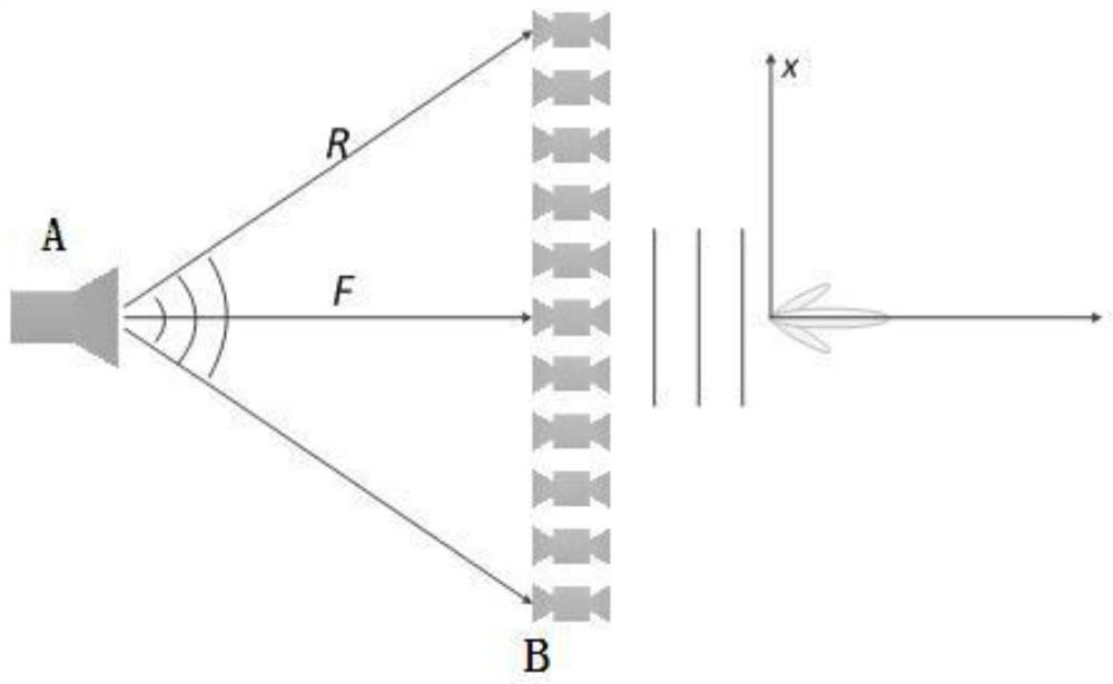
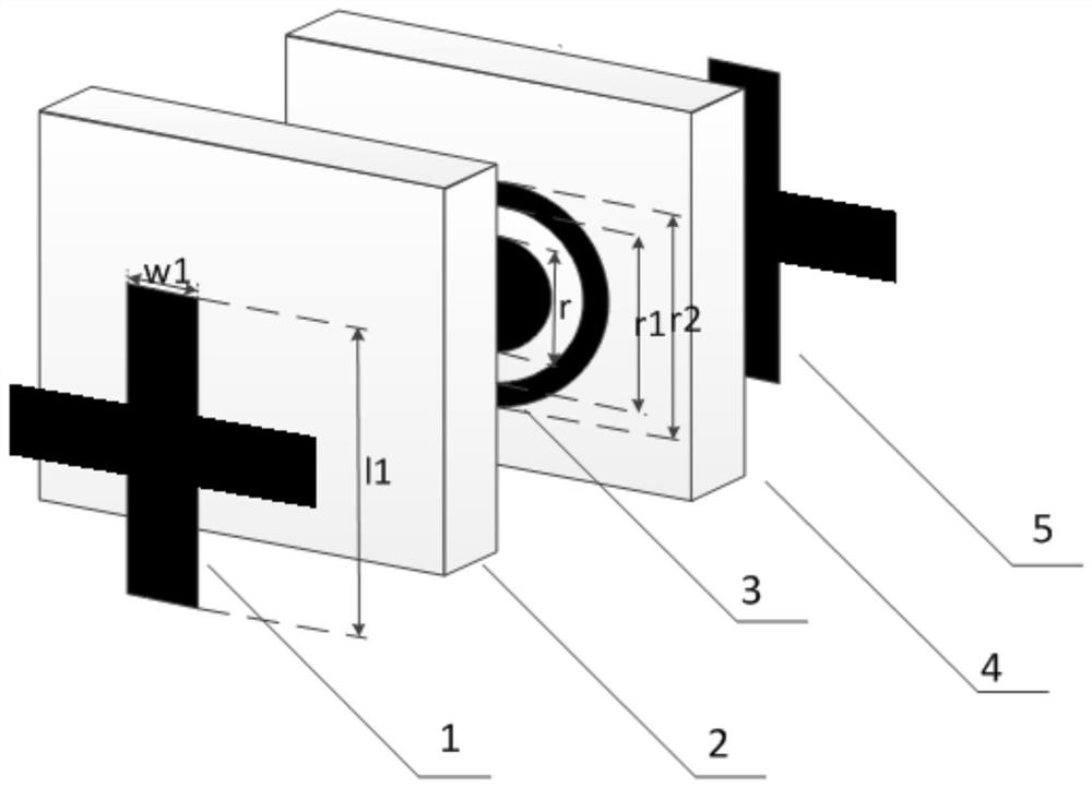
[0034] Such as Figure 1-10 As shown, the wide-beam planar lens antenna with variable beamwidth of the present invention is a metamaterial-based planar lens antenna, which has the characteristics of small size, light weight, easy integration and simple manufacture. It includes a horn feed antenna and a planar lens composed of several phase shifting units. The planar lens realizes the refraction of electromagnetic waves by setting gradient phases, thereby realizing the ch...


PUM


Abstract

The invention discloses a wide-beam plane lens antenna with variable beam width. The antennacomprises a horn feed source antenna and a plane lens, and the plane lens realizes the refraction of electromagnetic waves by setting a gradient phase, wherein on the basis of compensating a space phase caused by an optical path difference, an additional gradient phase delta n is added on the H surface of the antenna, the plane lens is composed of 51*51 phase shift units, each phase shift unit adopts two layers of media, the surfaces of the upper layer, the middle layer and the lower layer are coated with copper, and the thickness is very thin. In order to simplify the design and reduce the processing cost, eight phase shift units are selected to cover a phase shift range of 0-360 degrees. A beam broadening phase is introduced to enable the focusing performance of the lens on two main planes to be different so as to control the beam width, the phase shift required by each position is obtained according to a calculation formula of each point of the plane lens, and the phase shift units are arranged according to a specified phase distribution diagram to obtain the plane lens antenna with the specified beam width.

Description

technical field [0001] The invention relates to the technical field of antennas in passive devices, in particular to a wide-beam planar lens antenna with variable beam width. Background technique [0002] In recent years, intelligent driving methods such as assisted driving and automatic driving have brought opportunities for vigorous development of millimeter-wave automotive radar. Compared with traditional sensors, ultrasonic radar and infrared sensors, the 77Ghz millimeter wave automotive radar system performs well in complex weather conditions such as night, heavy rain and fog. Considering the space constraints of vehicles, automotive radar antennas are required to be lightweight, low profile and low cost. However, millimeter-wave radars are facing problems such as large size, small size, and poor performance. The planar lens array composed of a series of periodic subwavelength units has been favored for its high flexibility in beamforming and low cost. great concern o...

Claims


Application Information

Patent Timeline
Patent Type & Authority Applications(China)
IPC IPC(8): H01Q15/02H01Q15/00H01Q19/08H01Q13/02H01Q3/34H01Q1/00
CPCH01Q15/02H01Q19/08H01Q13/02H01Q3/34H01Q1/002H01Q15/0086
Inventor 李元杰李海明
Owner NANJING UNIV OF POSTS & TELECOMM
Why Eureka
Try Eureka