Phase-locked loop circuit of self-bias structure
A self-biasing, phase-locked loop technology, applied in the direction of electrical components, power automatic control, etc., can solve the problems of complex bias voltage or current routing, complex power supply topology, and noise performance changes, so as to simplify the power supply scheme and Frequency planning scheme, simple self-bias structure, and the effect of optimizing noise performance
- Summary
- Abstract
- Description
- Claims
- Application Information
AI Technical Summary
Problems solved by technology
Method used
Image

Examples
Embodiment Construction
[0035] The present invention will be described in further detail below in conjunction with the accompanying drawings.
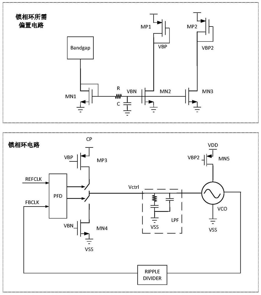
[0036] Such as figure 1 Shown is the traditional PLL structure and its typical bias circuit, including frequency detector, charge pump, loop filter, voltage controlled oscillator and frequency divider, the bias circuit includes bandgap reference and voltage reference bias place. It can be seen from the figure that the traditional charge pump phase-locked loop cannot work without reference voltage or current bias. In addition, as the required clock frequency in the SOC increases and the crystal frequency that needs to be supported increases, it is difficult for a single phase-locked loop to support all frequencies, which not only leads to an increase in the number of phase-locked loops, but also changes in the frequency of the traditional structure of the phase-locked loop will cause Bandwidth changes, which tend to worsen the overall noise of the PLL. The ...
PUM
 Abstract
Description
Claims
Application Information
 - Generate Ideas
- Intellectual Property
- Life Sciences
- Materials
- Tech Scout
- Unparalleled Data Quality
- Higher Quality Content
- 60% Fewer Hallucinations
Browse by: Latest US Patents, China's latest patents, Technical Efficacy Thesaurus, Application Domain, Technology Topic, Popular Technical Reports.
© 2025 PatSnap. All rights reserved.Legal|Privacy policy|Modern Slavery Act Transparency Statement|Sitemap|About US| Contact US: help@patsnap.com