Transformer winding direct current resistance back electromotive force suppression circuit
A technology of transformer winding and back electromotive force, applied in the direction of measuring resistance/reactance/impedance, circuit device, emergency protection circuit device for limiting overcurrent/overvoltage, etc. Damping oscillation can not be positively suppressed to achieve the effect of suppressing back electromotive force and ensuring safe operation
- Summary
- Abstract
- Description
- Claims
- Application Information
AI Technical Summary
Problems solved by technology
Method used
Image
Examples
Embodiment 1
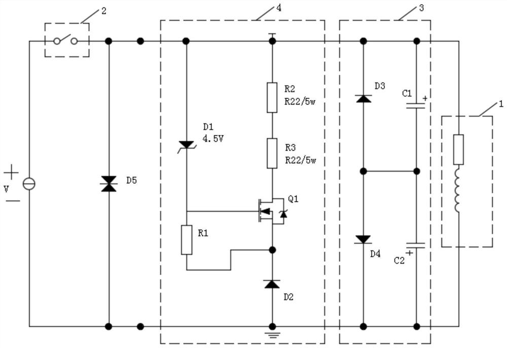
[0047] Please refer to figure 1 , Embodiment 1 of the present invention is:
[0048] In order to make this embodiment of the present invention and other embodiments easy to understand, here is a brief introduction to the basic principle of measuring the DC resistance of a transformer winding:
[0049] Such as figure 1 As shown, the transformer winding 1 in the circuit can be equivalent to an equivalent circuit in which the measured winding inductance and resistance are connected in series. A constant current source V is applied to the transformer winding 1 through a switching device 2 . After waiting for the circuit to stabilize, the DC resistance can be obtained. After cutting off the constant current source V, the inductance of the winding is very large, correspondingly a large counter electromotive force is generated. The counter electromotive force brings huge impact on the equipment, and even burns the equipment. Therefore, the present invention proposes the following s...
Embodiment 2
[0053] Please refer to figure 1 , the second embodiment of the present invention is:
[0054] A transformer winding 1 DC resistance counter electromotive force suppression circuit, on the basis of the first embodiment above, such as figure 1 As shown, the constant current source discharge circuit 4 includes a power resistor, a MOS transistor Q1, a first resistor R1, a second resistor R2, a third resistor R3, a first diode D1 and a second diode D2. Wherein, the anode of the first diode D1 and one end of the second resistor R2 are jointly used to connect the end of the transformer winding 1 connected to the anode of the constant current source V, and the other end of the second resistor R2 is connected to the MOS transistor Q1 through the third resistor R3 The drain of the first diode D1 is connected to the drain, the cathode of the first diode D1 is connected to one end of the first resistor R1 and the gate of the MOS transistor Q1 at the same time, and the other end of the fi...
Embodiment 3
[0055] Please refer to figure 1 , Embodiment three of the present invention is:
[0056] A transformer winding 1 DC resistance counter electromotive force suppression circuit, on the basis of the first or second embodiment above, such as figure 1 As shown, the bidirectional capacitor energy storage circuit 3 includes a third diode D3, a fourth diode D4, a first electrolytic capacitor CP1, and a second electrolytic capacitor CP2. The negative pole of the third diode D3 and the positive pole of the first electrolytic capacitor CP1 are commonly used to connect one end of the transformer winding 1, and the positive pole of the third diode D3 is connected with the negative pole of the second electrolytic capacitor CP2 and the fourth diode D4 at the same time. The positive pole of the second electrolytic capacitor CP2 is connected to the negative pole. The anode of the second electrolytic capacitor CP2 and the cathode of the fourth diode D4 are commonly used to connect the other e...
PUM
 Abstract
Description
Claims
Application Information
 - R&D
- Intellectual Property
- Life Sciences
- Materials
- Tech Scout
- Unparalleled Data Quality
- Higher Quality Content
- 60% Fewer Hallucinations
Browse by: Latest US Patents, China's latest patents, Technical Efficacy Thesaurus, Application Domain, Technology Topic, Popular Technical Reports.
© 2025 PatSnap. All rights reserved.Legal|Privacy policy|Modern Slavery Act Transparency Statement|Sitemap|About US| Contact US: help@patsnap.com

