
Motor back electromotive force high-voltage suppression method

A back-EMF, high-voltage suppression technology, applied in motor generator control, AC motor control, motor and other directions, can solve problems such as inability to reverse cycle power generation, inability to prevent locking to reduce danger, and inability to form electromagnetic braking.

Pending Publication Date: 2021-11-12
江苏银河数字技术有限公司 +1
View PDF1 Cites 0 Cited by
  • Summary
  • Abstract
  • Description
  • Claims
  • Application Information

AI Technical Summary

Problems solved by technology

Lithium batteries are sensitive to overvoltage, undervoltage, etc., and require sophisticated BMS protection boards to realize battery charging and discharging management. However, various motor protections on the market still have various problems
[0003] Such as the authorized announcement number is CN110912100A disclosed a kind of electric steering gear back EMF suppression circuit, although it realizes the circuit is simple and reliable, is conducive to the realization of miniaturization; Energy and energy consumption characteristics can fully absorb system energy, and at the same time provide transient energy output for motor start-up and commutation, with high reliability; impact response to system power supply through large-capacity capacitors, resistance switching speed, switch hysteresis protection, over-current protection, which improves the practicality of the system, but it does not solve the problems that the existing motor control process cannot generate electricity in reverse cycle, and cannot form the effect of electromagnetic braking, thereby suppressing the counter electromotive force, preventing locking and reducing risks, etc. For this reason, we A high-voltage suppression method for motor back EMF is proposed

Method used


Image

  • Motor back electromotive force high-voltage suppression method

Examples


Embodiment Construction

[0042] The following will clearly and completely describe the technical solutions in the embodiments of the present invention with reference to the accompanying drawings in the embodiments of the present invention. Obviously, the described embodiments are only some, not all, embodiments of the present invention. Based on the embodiments of the present invention, all other embodiments obtained by persons of ordinary skill in the art without making creative efforts belong to the protection scope of the present invention.

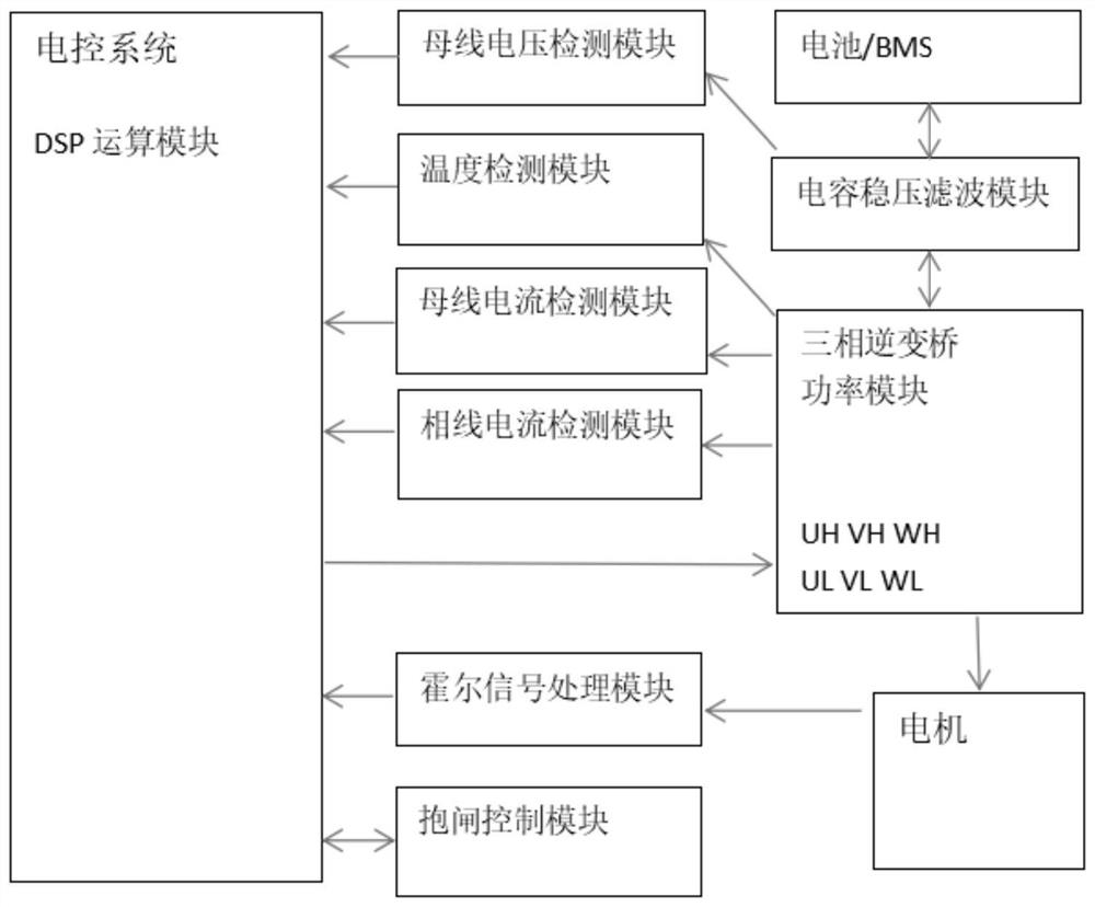
[0043] see figure 1, the present invention provides a technical solution: a method for suppressing high voltage of motor back electromotive force, including an electric control system, and the electric control system is electrically connected with a bus voltage detection module, a temperature detection module, a bus current detection module, and a phase line current detection module. A detection module, a Hall signal processing module, a brake control module a...


PUM


Abstract

The invention discloses a motor back electromotive force high-voltage suppression method. The method involves an electric control system, the electric control system is electrically connected with a bus voltage detection module, a temperature detection module, a bus current detection module, a phase line current detection module, a Hall signal processing module, a band-type brake control module and a three-phase inverter bridge power module, and the three-phase inverter bridge power module is electrically connected with a motor. The motor is electrically connected with the Hall signal processing module, the three-phase inverter bridge power module is electrically connected with a capacitor voltage-stabilizing filtering module, the capacitor voltage-stabilizing filtering module is electrically connected with a battery, the capacitor voltage-stabilizing filtering module is electrically connected with the bus current detection module, and the bus current detection module is electrically connected with the Hall signal processing module. The three-phase inverter bridge power module is electrically connected with the temperature detection module, the bus current detection module and the phase line current detection module. Electric energy can be recycled and stored, the capacitance voltage stabilization filtering module stores electric quantity, and braking control can be realized.

Description

technical field [0001] The invention belongs to the technical field of motors, and in particular relates to a method for suppressing a high voltage of a motor's counter electromotive force. Background technique [0002] With the further development of society and the requirements for carbon emissions, carbon neutrality and green goals, electrification and electrification have further penetrated into various fields, especially in transportation, logistics and other industries, and the proportion of vehicles powered by batteries is increasing. The main parts of such vehicles are batteries, electronic control systems, and motors. Lithium batteries are gradually replacing lead-acid batteries due to their high energy density and small size. Lithium batteries are sensitive to overvoltage, undervoltage, etc., and require sophisticated BMS protection boards to realize battery charging and discharging management. However, various motor protections on the market still have various pr...

Claims


Application Information

Patent Timeline
IPC IPC(8): H02P3/18H02P3/26H02P27/06B60L7/24
CPCH02P3/18H02P3/26H02P27/06B60L7/24Y02T10/64Y02T10/72
Inventor 汤栋良吴刚周国锋
Owner 江苏银河数字技术有限公司
Learn More