Motor driving device and driving method of the same

一种驱动装置、电动机的技术,应用在电动发电机控制、电气元件、控制系统等方向,能够解决无法达成电流衰减处理等问题,达到抑制反电动势、提高平均电流的效果

Active Publication Date: 2016-11-02
ROHM CO LTD
View PDF13 Cites 3 Cited by
  • Summary
  • Abstract
  • Description
  • Claims
  • Application Information

AI Technical Summary

Problems solved by technology

Therefore, on the whole, the coil current i10n increases with the passage of time, and the original current attenuation process cannot be achieved.

Method used


Image

  • Motor driving device and driving method of the same
  • Motor driving device and driving method of the same
  • Motor driving device and driving method of the same

Examples


no. 1 Embodiment

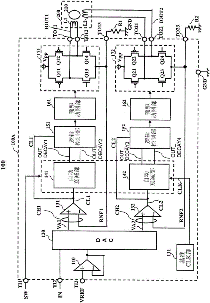
[0057] figure 1 A motor drive device 100 according to a first embodiment of the present invention is shown. The motor drive device 100 is used, for example, to drive a stepping motor or a DC motor, and is used, for example, as a drive unit of electronic equipment such as a printer, a facsimile machine, or a camera. figure 1 A motor drive device 100 applied to a stepping motor is shown. The motor drive device 100 includes an integrated circuit 100A and a stepping motor 200 .

[0058] In the integrated circuit 100A, for example, input terminals TI1 , TI2 , and TI3 ​​, output terminals TO11 , TO12 , TO13 , TO21 , TO22 , TO23 , and a ground terminal GND are prepared. A stepping motor 200 is connected to some of these external terminals. A mode selection signal SW for controlling the automatic attenuation units 141 and 142 described below is input to the input terminal TI1. The automatic attenuation units 141 and 142 will be described later. The control signal IN is input to...

no. 2 Embodiment

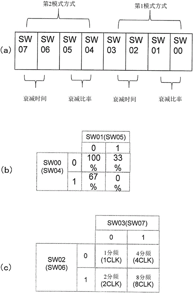
[0121] Figure 6 It is a timing chart of the motor drive device of the second embodiment of the present invention. The second example uses figure 1 , figure 2 The circuit shown is constructed with image 3 The default values ​​are determined by the addresses SW00-SW03 of the mode selection signal SW shown. This point is the same as the first embodiment, but the second mode in the second embodiment is different from the first embodiment in that not only the addresses SW04-SW07 of the mode selection signal SW are read, but also automatically changed. In the second embodiment, for example, the logic default values ​​of addresses SW00 to SW02 and SW03 of the mode selection signal SW are set to 0, 0, 0 and 0, respectively. which is, image 3 The mode selection signal SW shown in (a) controls two modes of the first mode mode and the second mode mode. However, the second embodiment adopts at least one mode, and the mode selection signal SW includes 4 bits of addresses SW00 to...

no. 3 Embodiment

[0140] Figure 8 It is a timing chart for explaining the operation of the motor drive device according to the third embodiment of the present invention. Like the first and second embodiments, the third embodiment is based on figure 1 , figure 2 circuit configuration and image 3 The default values ​​are determined by the addresses SW00-SW03 of the mode selection signal SW shown. The third embodiment is the same as the second embodiment, and the difference from the first embodiment is that the second mode mode is automatically changed without reading the addresses SW04 to SW07 of the mode selection signal SW. In the third embodiment, for example, the logic values ​​of the mode selection signals SW00 to SW02 and SW03 are set to 0, 0, 0 and 0, respectively. Of course, other settings can also be used. In addition, for example, a default value may be stored using a memory in the mode selection unit 41 . Period Y21 (time T50-T55) and period Y24 (time T65-T70) are processed i...


PUM


Abstract

A motor driving device and driving method of the same used to surely suppress the influence of counter electromotive force is provided. The motor driving device 100 includes an auto-decay portion 141. The auto-decay portion 141 controls a path of a electric current flow in a motor coil when supplying the electric current and when decaying the electric current. The influence of counter electromotive force generated in a stepping motor 200 can be suppressesed by the auto-decay portion 141 configured to control so that a ratio or an decay time of a slow decay mode and a fast decay mode of previous cycle is different from a ratio or an decay time of the slow decay mode and the fast decay mode of current cycle.

Description

technical field [0001] The invention relates to a motor driving device and a driving method of the motor driving device. Background technique [0002] Motors include various types of motors such as stepping motors and DC motors. For example, stepping motors are used to operate a paper feeding unit of a copier or a printer, or a reading unit of a scanner. [0003] Figure 12 Indicates the H-bridge circuit used in conventional stepping motor drive devices. The H-bridge circuit is arranged, for example, in front of the stepping motor, and is a circuit unit that directly drives the stepping motor. The H bridge circuit includes PMOS (P-channel Metal Oxide Semiconductor, P-type Metal Oxide Semiconductor) transistors Q11, Q12, and NMOS (N-channel Metal Oxide Semiconductor, N-type Metal Oxide Semiconductor) transistors Q13, Q14. Diodes D11, D12, D13, and D14 are body diodes structurally formed in each transistor. Assuming that the node connecting the transistor Q11 and the transi...

Claims


Application Information

Patent Timeline
Patent Type & Authority Applications(China)
IPC IPC(8): H02P8/12
CPCH02P8/12H02P8/18
Inventor 桥本浩树井上亮一
Owner ROHM CO LTD
Why Eureka
Try Eureka