
Novel efficient energy-saving wastewater treatment device and use method thereof

A high-efficiency, energy-saving, wastewater treatment technology, applied in multi-stage water treatment, water/sewage treatment, water treatment parameter control, etc. The effect of sludge reduction, not easy to block, easy to clean and maintain

Pending Publication Date: 2022-01-21
苏州市东方环境工程有限公司
View PDF0 Cites 0 Cited by
  • Summary
  • Abstract
  • Description
  • Claims
  • Application Information

AI Technical Summary

Problems solved by technology

[0003] The existing high-efficiency and energy-saving wastewater treatment devices have certain disadvantages in use. First, the sludge removal operation cannot be carried out well. The sludge contains harmful substances such as bacteria, pathogenic organisms, and parasite eggs, and the sludge is very unstable. It needs to be processed and disposed of in time, which is not conducive to people's use. In addition, it is prone to lime waste, cannot be cleaned and maintained well, and is prone to blockage, which has brought certain adverse effects to people's use process. Therefore, we propose a new type of high-efficiency and energy-saving wastewater treatment device and its application method

Method used


Image

  • Novel efficient energy-saving wastewater treatment device and use method thereof
  • Novel efficient energy-saving wastewater treatment device and use method thereof
  • Novel efficient energy-saving wastewater treatment device and use method thereof

Examples


Embodiment 1

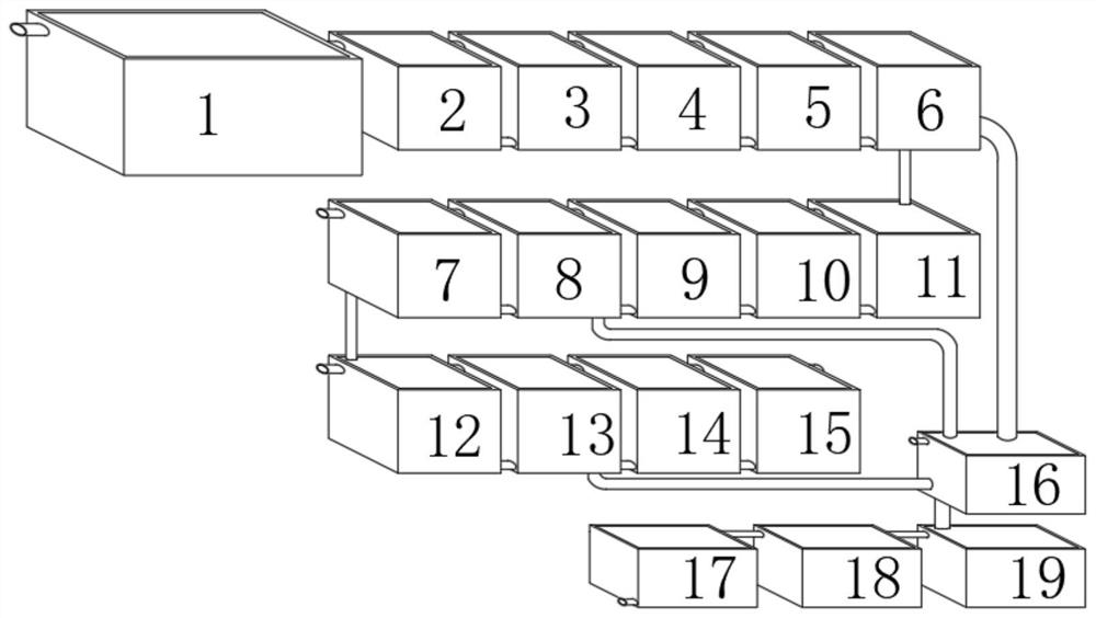
[0034] Such as Figure 1-6 As shown, a new high-efficiency and energy-saving wastewater treatment device includes a wastewater storage tank 1, one end of the wastewater storage tank 1 is connected to a regulating tank body 2, and one end of the regulating tank body 2 is connected to a pH pre-adjusting tank body 3, and the pH pre-adjusting tank One end of the body 3 is connected with a No. 1 reaction pool 4, one end of the No. 1 reaction pool 4 is connected with a No. flocculation pool 5, one end of the No. 1 flocculation pool 5 is connected with a No. 1 physicochemical sedimentation pool 6, and one end of the No. 1 physicochemical sedimentation pool 6 is connected with a The neutralization tank body 11 is connected with the sludge thickening tank 16, and one end of the neutralization tank body 11 is connected with the anoxic tank body 10, and one end of the anoxic tank body 10 is connected with the aerobic tank body 9, and one end of the aerobic tank body 9 is connected with T...

Embodiment 2

[0045] On the basis of Example 1, as Figure 1-6 As shown, a new high-efficiency and energy-saving wastewater treatment device includes a wastewater storage tank 1, one end of the wastewater storage tank 1 is connected to a regulating tank body 2, and one end of the regulating tank body 2 is connected to a pH pre-adjusting tank body 3, and the pH pre-adjusting tank One end of the body 3 is connected with a No. 1 reaction pool 4, one end of the No. 1 reaction pool 4 is connected with a No. flocculation pool 5, one end of the No. 1 flocculation pool 5 is connected with a No. 1 physicochemical sedimentation pool 6, and one end of the No. 1 physicochemical sedimentation pool 6 is connected with a The neutralization tank body 11 and the sludge thickening tank 16, one end of the neutralization tank body 11 is connected with the anoxic tank body 10, one end of the anoxic tank body 10 is connected with the aerobic tank body 9, and one end of the aerobic tank body 9 is connected with T...

Embodiment 3

[0056] On the basis of Example 2, such as Figure 1-6 As shown, a new high-efficiency and energy-saving wastewater treatment device includes a wastewater storage tank 1, one end of the wastewater storage tank 1 is connected to a regulating tank body 2, and one end of the regulating tank body 2 is connected to a pH pre-adjusting tank body 3, and the pH pre-adjusting tank One end of the body 3 is connected with a No. 1 reaction pool 4, one end of the No. 1 reaction pool 4 is connected with a No. flocculation pool 5, one end of the No. 1 flocculation pool 5 is connected with a No. 1 physicochemical sedimentation pool 6, and one end of the No. 1 physicochemical sedimentation pool 6 is connected with a The neutralization tank body 11 and the sludge thickening tank 16, one end of the neutralization tank body 11 is connected with the anoxic tank body 10, one end of the anoxic tank body 10 is connected with the aerobic tank body 9, and one end of the aerobic tank body 9 is connected wi...


PUM


Abstract

The invention discloses a novel efficient energy-saving wastewater treatment device and a using method thereof.The novel efficient energy-saving wastewater treatment device comprises a wastewater storage tank, one end of the wastewater storage tank is connected with an adjusting tank body, one end of the adjusting tank body is connected with a pH pre-adjusting tank body, one end of the pH pre-adjusting tank body is connected with a first reaction tank, and one end of the first reaction tank is connected with a first flocculation tank. According to the novel high-efficiency energy-saving wastewater treatment device and the using method thereof, a precipitated sludge reflux process is set, chemicals in sludge react with wastewater to form denser crystal particles, so that sludge reduction is realized, a channel is arranged for water supply through a circulating pipe in the process through hydraulic fine adjustment, the device has the advantages of being easy to clean and maintain and not prone to being blocked, a high pressure diaphragm dehydrator is used, the water content of sludge subjected to filter pressing of the dehydrator can reach about 70% at least, the water content of the sludge subjected to filter pressing of a common box type dehydrator reaches 80%, and the treatment load of a follow-up dryer is reduced.

Description

technical field [0001] The invention relates to the field of wastewater treatment, in particular to a novel high-efficiency and energy-saving wastewater treatment device and a method for using the same. Background technique [0002] The high-efficiency and energy-saving wastewater treatment device is a supporting equipment for wastewater treatment. In industrial production, a certain amount of wastewater will be generated. The daily wastewater production volume is 400m3 / d. Considering the unevenness of drainage, the designed treatment capacity is 16m3 / d h. During the sewage treatment process, a certain amount of sludge will be produced, which needs to be treated regularly. With the continuous development of science and technology, people have higher and higher requirements for the manufacturing process of high-efficiency and energy-saving wastewater treatment devices. [0003] The existing high-efficiency and energy-saving wastewater treatment devices have certain disadvanta...

Claims


Application Information

Patent Timeline
Patent Type & Authority Applications(China)
IPC IPC(8): C02F9/14C02F11/12C02F11/122C02F11/13
CPCC02F9/00C02F11/12C02F11/122C02F11/13C02F1/66C02F1/5281C02F2001/007C02F3/30C02F1/5236C02F1/56C02F2301/08C02F2209/005C02F2209/18C02F2303/06C02F2303/14
Inventor 周良明吉剑张新锋袁静
Owner 苏州市东方环境工程有限公司
Learn More