Tray device for growing crystals by horizontal directional crystallization method and use method

A technology of growing crystals and horizontal orientation, applied in the directions of single crystal growth, crystal growth, single crystal growth, etc., can solve problems such as temperature field asymmetry, increased crystal stress, warping deformation, etc., to achieve the effect of eliminating deformation and suppressing guide rails Deformation, long-term flat effect

Pending Publication Date: 2022-01-21
CHINA ELECTRONICS TECH GRP NO 26 RES INST
View PDF0 Cites 0 Cited by
  • Summary
  • Abstract
  • Description
  • Claims
  • Application Information

AI Technical Summary

Problems solved by technology

In the current scheme, the tray is directly placed on the guide rail. When the guide rail moves slowly at high temperature, the tray is easy to move relative to the guide rail, causing the crucible to deviate from the central axis, resulting in an asymmetrical temperature field, which seriously affects the quality of the crystal. At the same time, the crucible is also placed directly On the tray, it

Method used


Image

  • Tray device for growing crystals by horizontal directional crystallization method and use method
  • Tray device for growing crystals by horizontal directional crystallization method and use method

Examples


Embodiment 1

[0038] Nd:YAG crystals were grown using a tray device for crystal growth by horizontal oriented crystallization.

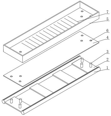
[0039]The guide rail is composed of two cylindrical molybdenum rods. There are 4 horizontal plates between the two molybdenum rods. There are 3 positioning columns on the horizontal plates at both ends of the guide. The height of the positioning columns is 5mm and the diameter is 4mm. The thickness of the buffer plate is 1mm, the length is 500mm, and the width is 120mm. The size of the bottom of the tray is 500×120mm, and the height of the tray wall is 50mm. There is a positioning hole at the corresponding position of the buffer plate and the tray, which has the same size as the positioning column. The size of the positioning hole relative to the positioning column has a positive tolerance, and the tolerance is not greater than 0.2mm. Tungsten wire diameter is 0.5mm.

[0040] When in use, first install the buffer plate on the guide rail from the vertical directi...

Embodiment 2

[0042] Large-sized Yb:YAG crystals were grown using a tray device for crystal growth by horizontal oriented crystallization.

[0043] The guide rail is composed of two cylindrical molybdenum rods. There are 5 horizontal plates between the two molybdenum rods. There are 4 positioning columns on the horizontal plates at both ends of the guide rail. The height of the positioning columns is 8mm and the diameter is 5mm. The thickness of the buffer plate is 1mm, the length is 600mm, and the width is 220mm. The size of the bottom of the tray is 600×220mm, and the height of the tray wall is 60mm. There is a positioning hole at the corresponding position of the buffer plate and the tray, which has the same size as the positioning column. The size of the positioning hole relative to the positioning column has a positive tolerance, and the tolerance is not greater than 0.2mm. Tungsten wire diameter is 0.8mm.

[0044] When in use, first install the buffer plate on the guide rail from th...


PUM

PropertyMeasurementUnit
Heightaaaaaaaaaa
Diameteraaaaaaaaaa
Thicknessaaaaaaaaaa

Abstract

The invention discloses a tray device for growing crystals by a horizontal directional crystallization method and a use method, the tray device comprises a guide rail and a tray placed on the guide rail, and a buffer plate is arranged between the guide rail and the tray; a plurality of transversely-arranged tungsten wires are evenly laid on the upper surface of the tray in the length direction at intervals so that a crucible to be placed can be placed on the tray through the tungsten wires, the guide rail is composed of two guide rail rods and a plurality of transverse plates evenly installed between the two guide rail rods, and a plurality of positioning columns are evenly and fixedly installed on the surfaces of the transverse plates located at the two ends at intervals respectively; Aand positioning holes through which the corresponding positioning columns penetrate are formed in the surfaces of the buffer plate and the tray in a one-to-one correspondence manner. The stability of the tray during guide rail moving is effectively improved, the tray is prevented from being bonded with the bottom of the crucible, meanwhile, deformation of the tray and the guide rail is reduced, the service life of the tray and the guide rail is prolonged, and the crystal growth quality is improved.

Description

technical field [0001] The invention relates to the technical field of crystal material preparation, in particular to a tray device for growing crystals by a horizontal oriented crystallization method and a usage method. Background technique [0002] Large-size slab Yb:YAG / Nd:YAG laser crystals are currently the main gain medium used in high-power solid-state lasers. They are used in laser weapons, laser cutting and other fields. National defense industry, industrial production, etc. are of great significance. The horizontal oriented crystallization method is a crystal growth method suitable for large-scale slab laser crystals. The laser crystals grown by this method have the advantages of low cost, high crystal quality, no core side center, and small processing allowance. [0003] Laser crystals have strict requirements on crystal quality, and high-power lasers require high-quality laser crystals without any defects such as cracks, clouds, bubbles, inclusions, and flash pa...

Claims


Application Information

Patent Timeline
IPC IPC(8): C30B11/00C30B29/28
CPCC30B11/00C30B29/28
Inventor 顾跃丁雨憧徐扬田野陈佳佳
Owner CHINA ELECTRONICS TECH GRP NO 26 RES INST
Why Eureka
Try Eureka