
Maintenance system for high-energy water recovery of supercritical unit

A supercritical unit and water recovery technology, which is applied in separation methods, heating systems, chemical instruments and methods, etc., can solve the problems of strict chemical index requirements, difficult maintenance of high-energy water systems, and uncertain maintenance time of high-energy water recovery systems, etc. problem, to achieve the effect of simple operation method

Pending Publication Date: 2022-01-21
XIAN THERMAL POWER RES INST CO LTD +1
View PDF8 Cites 1 Cited by
  • Summary
  • Abstract
  • Description
  • Claims
  • Application Information

AI Technical Summary

Problems solved by technology

[0004] From the above analysis, it can be seen that the high-energy water recovery system not only has the characteristics of uncertain maintenance time, strict requirements on chemical indicators after maintenance, and the system needs to be put into operation as soon as possible, it is difficult to maintain the high-energy water system.
At present, the high-energy water recovery system has not seen the introduction of relevant maintenance methods. The existing dry anti-corrosion method and wet anti-corrosion method for the unit cannot be simply applied. The maintenance method should be based on the system composition and interval of the high-energy water recovery system According to the characteristics of sex work, formulate corresponding maintenance methods

Method used


Image

  • Maintenance system for high-energy water recovery of supercritical unit
  • Maintenance system for high-energy water recovery of supercritical unit

Examples


Embodiment Construction

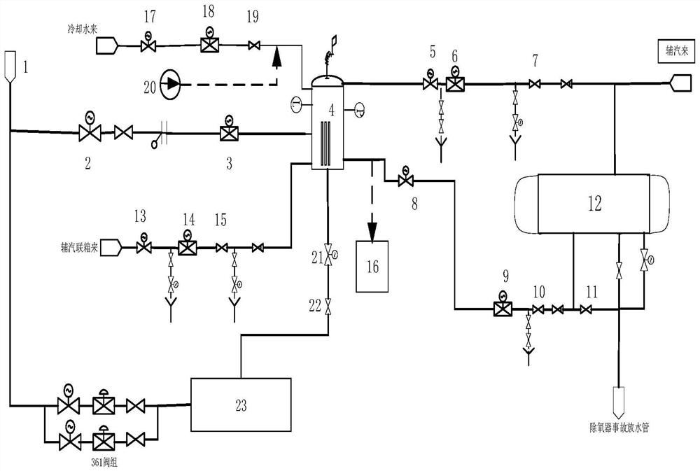
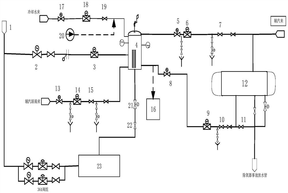
[0034] The following is an example of a high-energy water recovery system set up by a 350MW supercritical unit (main steam pressure 24MPa, main steam temperature 566°C). The expansion volume of the high-energy water recovery system is 10m 3 , The design rated recovery of high-energy water is 100t / h. After the high-energy water is expanded through the expansion vessel, the steam and water are recovered to the deaerator respectively. The present invention is described in further detail in conjunction with the accompanying drawings.

[0035] refer to figure 1 , a maintenance system for recovering high-energy water of a supercritical unit, comprising: boiler start-up separator water storage tank 1, boiler start-up separator water storage tank 1, boiler start-up separator water storage tank 1 through high-energy water electric isolation valve 2, high-energy water inlet water The flow regulating valve 3 is connected with the high-energy water expansion vessel 4, and the saturated w...


PUM


Abstract

The invention discloses a maintenance system for high-energy water recovery of a supercritical unit and a method. The system comprises a boiler starting separator water storage tank, the boiler starting separator water storage tank communicates with a high-energy water flash tank, the upper part of the high-energy water flash tank is communicated with a deaerator, a high-energy water dosing pump is arranged on the high-energy water flash tank and a cooling water inlet pipeline, a sampler is arranged on a pipeline from the high-energy water flash tank to the deaerator, and the bottom of the high-energy water flash tank communicates with the boiler starting separator water storage tank. According to the intermittent working characteristic of the high-energy water recovery system, two maintenance modes of a hot standby method and an ammonia water method are adopted, specifically, (a) when the unit needs frequent peak regulation and the interval time of putting into the high-energy water system is less than or equal to 7 days, the hot standby method is selected for maintenance; (b) when the next peak regulation interval of the unit is larger than 7 days, the ammonia water method is selected for maintenance, the two maintenance methods conform to the intermittent working characteristic of the high-energy water system, the operation method is simple, convenient and effective, it is ensured that the high-energy water system can be put into operation in time, and the peak regulation requirement faced by the unit is met.

Description

technical field [0001] The invention belongs to the technical field of heat supply and energy saving of thermal power generation equipment, and in particular relates to a maintenance system and method for recovering high-energy water of a supercritical unit. Background technique [0002] The high-energy water recovery technology for ultra-(ultra)critical units is a technology suitable for ultra-(ultra)critical units in the deep peak-shaving operation state, and when the unit is in a wet state. Water separation for recovery can effectively improve the economics of deep peak-shaving operation of the unit, and has a very good application prospect for ultra-supercritical units with deep peak-shaving requirements. [0003] Although the thermal power unit plays the role of supporting the supply in the power grid, it is impossible to predict when the thermal power unit will peak and the duration of peak regulation. The high-energy water recovery system cannot be put into use when t...

Claims


Application Information

Patent Timeline
Patent Type & Authority Applications(China)
IPC IPC(8): F22B37/26F22B37/50F22B37/46F22B37/48F22D1/50F24D19/00F01D15/10
CPCF22B37/26F22B37/50F22B37/46F22B37/48F22D1/50F24D19/00F01D15/10
Inventor 居文平曾立飞马汀山屈杰高登攀陈锋李辉
Owner XIAN THERMAL POWER RES INST CO LTD
Learn More