
Alkaline electrolyte regeneration

An electrolytic regeneration, electrolyte technology, applied in the direction of alkaline electrolyte, aqueous electrolyte, electrolytic components, etc., can solve problems such as reducing the efficiency of metal-air power supply

Pending Publication Date: 2022-01-21
PHINERGY
View PDF8 Cites 0 Cited by
  • Summary
  • Abstract
  • Description
  • Claims
  • Application Information

AI Technical Summary

Problems solved by technology

[0002] Metal-air electrochemical power sources, especially aluminum-air batteries and fuel cells with alkaline electrolytes, produce metal hydroxides (e.g., aluminum hydroxide) due to metal dissolution from the anode, which reduces the efficiency, and requires replacement of the electrolyte solution

Method used


Image

  • Alkaline electrolyte regeneration
  • Alkaline electrolyte regeneration
  • Alkaline electrolyte regeneration

Examples


Embodiment

[0069] In the following, non-limiting examples for the preparation and operation of system 100 and method 200 are provided. These examples illustrate the applicability of the disclosed method 200 and system 100 and do not limit the scope of the invention.

[0070] Example 1 - System Settings

[0071] The system consists of two chambers (made of PMMA, one for the anolyte and one for the catholyte, 2.5 L each. The dimensions of each tank are 10 x 10 x 16 cm and a membrane separates the two chambers ). A peristaltic pump (Hontile Industrial Co.LTD) circulated the electrolyte through the electrolytic membrane tank. The electrolyzer was connected to a power source (Mancon Hcs3042) where the voltage / current was recorded by a computer and the pH of the anolyte compartment was also continuously monitored.

[0072] A separate beaker containing 100 mL of filtered spent electrolyte (SE) was placed adjacent to the anolyte compartment. The composition of the spent electrolyte is as fol...

Embodiment 2

[0075] Embodiment 2-electrolytic membrane tank device

[0076] 99.6% pure nickel plate is used as the anode and the cathode is made by Phinergy TM Production of air cathodes. The membrane is a commercially available N551WX K + Nafion membrane. Zinc wires wrapped in Teflon sleeves were placed adjacent to both sides of the membrane. The anode and cathode potentials (vs. Zn / ZnO) were continuously recorded.

Embodiment 3

[0077] Example 3 - Parameters and Experimental Conditions Examined I

[0078] Electrolyzer at room temperature 100mA / cm 2 (normalized to membrane surface area) was run at constant current. Before adding SE, the pH of the anolyte was first adjusted to a lower value (−10.5). The addition of SE was manually adjusted to maintain the pH at 9-10.5.

[0079] The parameters evaluated in this experiment were: the potential of the anode and cathode (relative to the reference electrode); the iR drop caused by the membrane (and solution resistance); the corrosion current efficiency (CCE); and the water transport upon potential application ( Electroosmotic resistance coefficient, in mL / mol K + or mol / mol K + ).

[0080] In further experiments, using both the static electrolytic membrane electrolyzer and the system described above, we were able to demonstrate 100% CCE. In addition, SE was dropped separately into the portion taken from the anolyte chamber (ie not during potential appli...


PUM

PropertyMeasurementUnit
particle sizeaaaaaaaaaa

Abstract

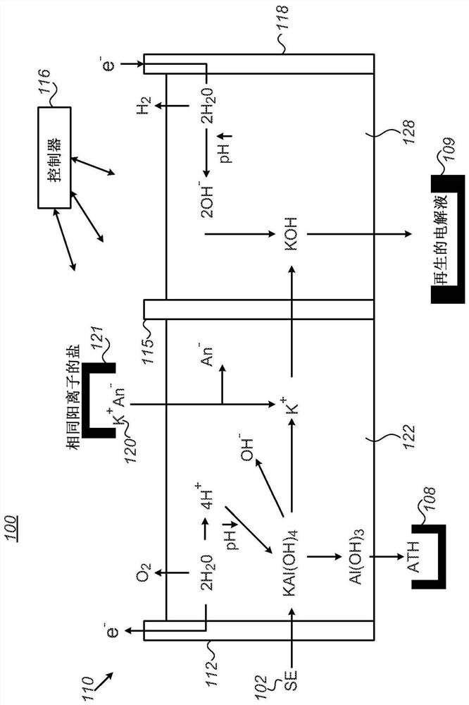
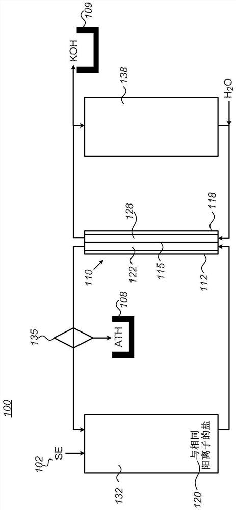
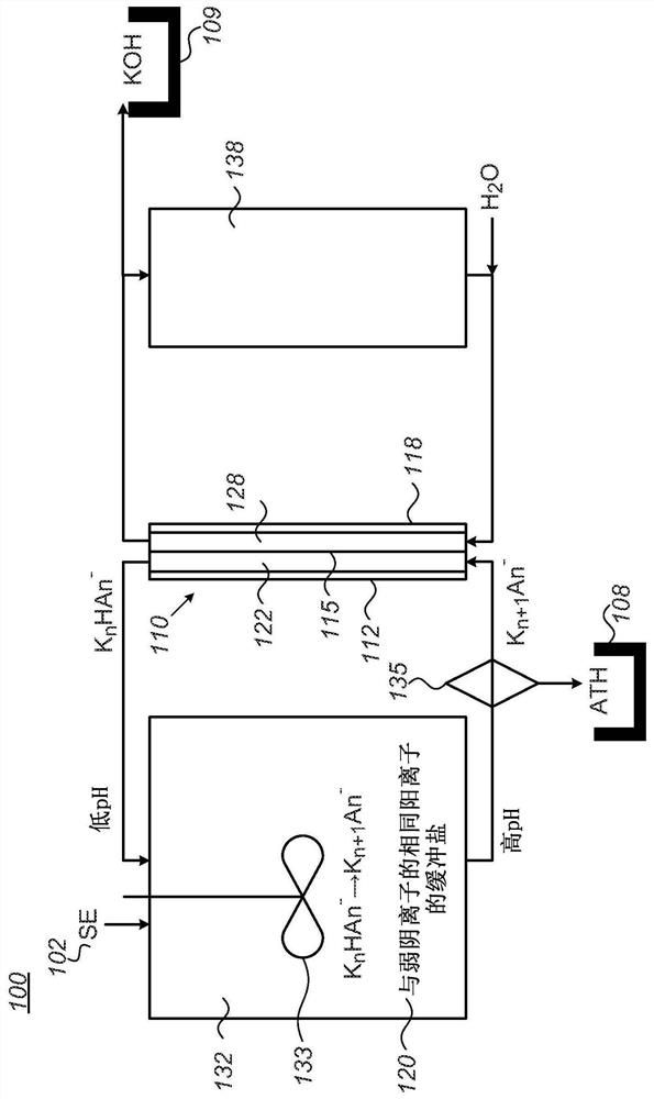
Methods and systems for electrolyte regeneration are provided, which regenerate a spent alkaline electrolyte (SE) comprising dissolved aluminum hydrates from an aluminum-air battery, by electrolysis, to precipitate aluminum tri-hydroxide (ATH) and form regenerated alkaline electrolyte, and adding a same-cation salt to an anolyte used in the electrolysis to supplant a corresponding electrolyte cation. The regeneration may be carried out continuously and further comprise mixing the SE and the same-cation salt in a salt tank configured to deliver the anolyte, removing the regenerated alkaline electrolyte from a catholyte tank configured to deliver the catholyte, and filtering the ATH from a solution delivered from the salt tank to the anolyte. Optionally, the salt may be a buffering salt, and in some cases chemical reactions may be used to enhance the regeneration by electrolysis.

Description

technical field [0001] The present invention relates to the field of electrolyte treatment, and more particularly to the regeneration of spent electrolyte as a product of, for example, the operation of metal-air batteries or other chemical processes. Background technique [0002] Metal-air electrochemical power sources, especially aluminum-air batteries and fuel cells with alkaline electrolytes, produce metal hydroxides (e.g., aluminum hydroxide) due to metal dissolution from the anode, which reduces the efficiency, and requires replacement of the electrolyte solution. Furthermore, metal hydroxides are by-products of many useful chemical processes (e.g. the Bayer process for alumina production, the dissolution of aluminum metal in bases e.g. for hydrogen production, aluminum anodization processes, etc., all produce bases metal aluminate solution). Contents of the invention [0003] The following is a simplified summary to provide an initial understanding of the invention...

Claims


Application Information

Patent Timeline
Patent Type & Authority Applications(China)
IPC IPC(8): H01M6/50B60L50/60C23G1/36C25B1/16B60L58/10H01M10/42H01M10/12
CPCB60L50/60C25B1/16Y02T10/70Y02P70/50C25B9/19H01M10/54H01M2300/0014H01M12/08C25B1/01C25B15/081C25D21/16C01F11/18B60L58/10C23G1/36H01M10/12H01M10/42H01M6/50C25B15/02C25B15/08H01M12/02H01M12/06C25B15/083C25B15/087H01M6/5077B01D61/44
Inventor 伊利亚·亚库波夫阿维耶尔·达尼诺马克·威弗肖恩·亨利·加拉格尔尼古拉·梅内加佐
Owner PHINERGY
Learn More