MEMS vacuum gauge and preparation method thereof

A vacuum gauge and substrate technology, applied in vacuum gauges, welding equipment, precision positioning equipment, etc., can solve the lower limit of vacuum degree limit measurement, the upper limit value of vacuum degree limit measurement, and the increase in specific gravity of resistance heating body, etc. problems, to achieve the effect of improving reliability, good consistency, and small size

Active Publication Date: 2022-01-28
南京元感微电子有限公司
View PDF5 Cites 4 Cited by
  • Summary
  • Abstract
  • Description
  • Claims
  • Application Information

AI Technical Summary

Problems solved by technology

[0003] In the existing MEMS Pirani vacuum gauge, when the vacuum pressure is low, the proportion of the heat dissipation of the resistance heating body through the substrate increases, and the accuracy of the vacuum gauge decreases, thus limiting the lower limit of the measured vacuum degree
However, due to the small size of the existing MEMS capacitive film vacuum gauge, the vacuum gauge needs to use a large aspect ratio pressure sensitive film and a very small electrode spacing to ensure a sufficiently high sensitivity and a sufficiently large capacitance, thus limiting the upper limit of the measured vacuum degree. value

Method used


Image

  • MEMS vacuum gauge and preparation method thereof
  • MEMS vacuum gauge and preparation method thereof
  • MEMS vacuum gauge and preparation method thereof

Examples


Embodiment Construction

[0042] In order to enable those skilled in the art to better understand the technical solutions of the present invention, the present invention will be further described in detail below in conjunction with the accompanying drawings and specific embodiments.

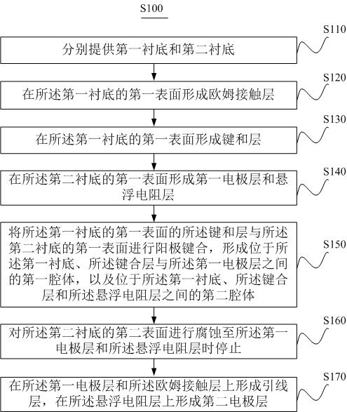
[0043] Such as figure 1 As shown, one aspect of the present invention provides a preparation method S100 of a MEMS vacuum gauge, and the packaging method S100 includes:

[0044] S110. Provide a first substrate and a second substrate respectively.

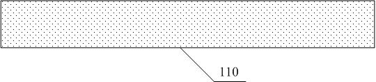
[0045] Specifically, such as image 3 As shown, in this embodiment, a low-resistance silicon wafer with a thickness of 200 μm to 1000 μm is selected as the first substrate 110 , and more preferably, a low-resistance silicon wafer with a thickness of 300 μm is used as the first substrate 110 . Such as Figure 7 As shown, in this embodiment, single crystal silicon with a thickness of 200 μm to 1000 μm is selected as the second substrate 120 , and more preferably, an N-type sil...


PUM

PropertyMeasurementUnit
thicknessaaaaaaaaaa
thicknessaaaaaaaaaa
thicknessaaaaaaaaaa

Abstract

The invention provides an MEMS vacuum gauge and a preparation method thereof. The method comprises the following steps of providing a first substrate and a second substrate, forming an ohmic contact layer on the first surface of the first substrate, forming a bonding layer on the first surface of the first substrate, forming a first electrode layer and a suspension resistance layer on the first surface of the second substrate, performing anodic bonding on the bonding layer on the first surface of the first substrate and the first surface of the second substrate to form a first cavity located among the first substrate, the bonding layer and the first electrode layer and a second cavity located among the first substrate, the bonding layer and the suspension resistance layer, corroding the second surface of the second substrate until the first electrode layer and the suspension resistance layer are reached, and forming a lead layer on the first electrode layer and the ohmic contact layer, and forming a second electrode layer on the suspension resistance layer. According to the method, the measuring range of the MEMS vacuum gauge is effectively improved, and the vacuum gauge has the advantages of being small in size, high in precision, good in consistency, easy to manufacture in batches and low in cost.

Description

technical field [0001] The invention belongs to the technical field of vacuum measurement, and in particular relates to a MEMS vacuum gauge and a preparation method thereof. Background technique [0002] The branch of the barometer in the high vacuum environment is the vacuum gauge. The appearance of the micro-electromechanical system (MEMS, Micro-Electro-Mechanical System) has made the vacuum gauge miniaturized. The MEMS Pirani vacuum gauge uses the heat dissipation of the resistance heating body under high vacuum. The correlation between the velocity and the surrounding gas pressure is measured. The MEMS capacitive film vacuum gauge uses the external pressure to deform the film, which causes the capacitance of the sensitive capacitor composed of the film and the fixed electrode to change, and measures the pressure of the vacuum system by measuring the capacitance and calibrating. Pirani vacuum gauges and capacitive film vacuum gauges based on MEMS technology are widely us...

Claims


Application Information

Patent Timeline
Patent Type & Authority Applications(China)
IPC IPC(8): B81C1/00B81C3/00B81B7/00B81B7/02G01L21/00
CPCB81C3/001B81C1/00134B81B7/02B81B7/0009G01L21/00B81B2201/0221
Inventor 王广猛史晓晶柳俊文
Owner 南京元感微电子有限公司
Why Eureka
Try Eureka