
Laser device with high-power multi-mode beam combiner

A laser, high-power technology, applied in the field of lasers, can solve the problems of laser damage, formation of a spot belt ring, and reduction in the utilization rate of coolant, and achieve the effect of improving the homogenization effect of the spot, improving the heat exchange efficiency, and improving the spatial distribution.

Active Publication Date: 2022-02-01
GW (SHANGHAI) LASER TECH CO LTD
View PDF14 Cites 0 Cited by
  • Summary
  • Abstract
  • Description
  • Claims
  • Application Information

AI Technical Summary

Problems solved by technology

[0002] Fiber-coupled output lasers will generate heat due to long-term work during use. The existing cooling method is to cool down through cooling fluid or fans, but in the process of using cooling fluid alone, the flow of cooling fluid will cause The cooling liquid in contact with the device absorbs a large amount of heat, and the cooling liquid that is not in contact with the device cannot participate in the cooling and cooling process well, which reduces the utilization rate of the cooling liquid and limits the absorption of heat by the cooling liquid. Causes damage to the laser and affects its normal use; while the traditional fan cooling effect is not good and cannot meet the long-term cooling needs, so the existing technology cannot meet people's cooling needs
[0003] Fiber-coupled output lasers have attracted people's attention because of their flexible use and excellent output spot mode. If the light cannot be eliminated, it will be reflected into the laser through the optical fiber, which will affect the stability of the laser operation
[0004] Moreover, since the optical fiber used for high-power transmission is a multimode optical fiber, the distribution of optical power is affected by the high-order mode of the output beam, resulting in problems such as spot rings, dark centers, or flashlight phenomena.

Method used


Image

  • Laser device with high-power multi-mode beam combiner
  • Laser device with high-power multi-mode beam combiner
  • Laser device with high-power multi-mode beam combiner

Examples


Embodiment Construction

[0035]The following will clearly and completely describe the technical solutions in the embodiments of the present invention with reference to the accompanying drawings in the embodiments of the present invention. Obviously, the described embodiments are only some, not all, embodiments of the present invention. Based on the embodiments of the present invention, all other embodiments obtained by persons of ordinary skill in the art without making creative efforts belong to the protection scope of the present invention.

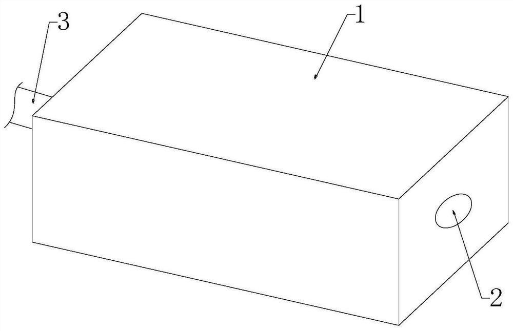
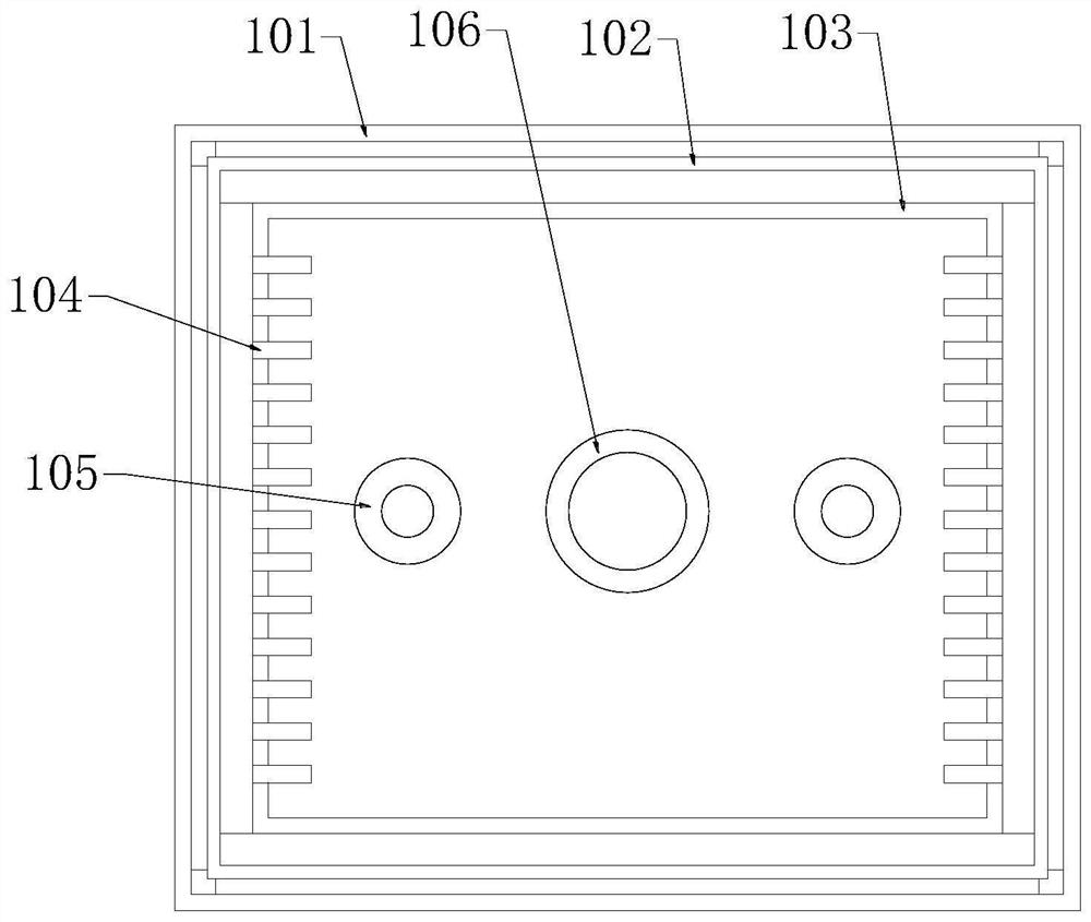
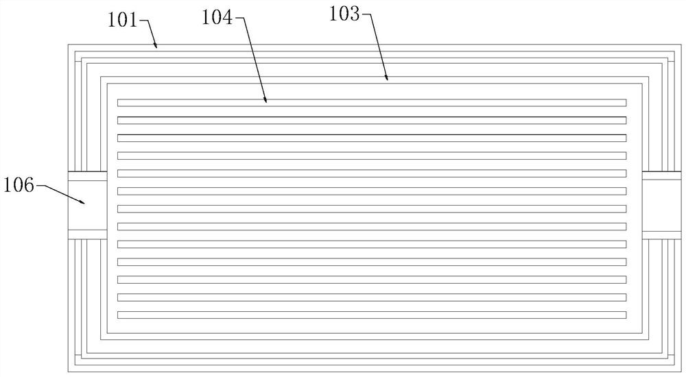
[0036] see Figure 1-Figure 10 The present invention provides a technical solution: a laser with a high-power multi-mode beam combiner, the laser of the multi-mode beam combiner includes a laser housing 1, and the laser housing 1 is internally provided with a laser source group 4 and a beam combiner 5 , an isolator 6, a homogenizing mirror 7, a zoom mechanism 8, a power line 3 is connected to the laser source group 4, the laser source group 4 is connected to th...


PUM


Abstract

The invention discloses a laser device with a high-power multi-mode beam combiner, and belongs to the technical field of laser devices. The laser device with the multi-mode beam combiner comprises a laser shell, wherein the lase shell is internally provided with a laser source group, a beam combiner, an isolator, a homogenizing mirror and a zooming mechanism, the laser source group is connected with a power line, the laser source group is connected with the beam combiner through an optical fiber, the beam combiner is connected with the isolator through an optical fiber, the isolator transmits laser to the homogenizing mirror through an optical fiber, the homogenizing mirror homogenizes the laser, the homogenizing mirror transmits the homogenized laser to the zooming mechanism, the zooming mechanism focuses the laser, and the zooming mechanism outputs the focused laser through goggles. The optical fiber is provided with a bending pipe, the bending angle and shape of the optical fiber are adjusted through the bending pipe, the spatial distribution of laser beams output by the optical fiber is improved, the light spot homogenizing effect is achieved, and the light spot homogenizing effect is improved through mutual cooperation of the bending pipe and the homogenizing mirror.

Description

technical field [0001] The invention relates to the technical field of lasers, in particular to a laser with a high-power multimode beam combiner. Background technique [0002] Fiber-coupled output lasers will generate heat due to long-term work during use. The existing cooling method is to cool down through cooling fluid or fans, but in the process of using cooling fluid alone, the flow of cooling fluid will cause The cooling liquid in contact with the device absorbs a large amount of heat, and the cooling liquid that is not in contact with the device cannot participate in the cooling and cooling process well, which reduces the utilization rate of the cooling liquid and limits the absorption of heat by the cooling liquid. It causes damage to the laser and affects its normal use; and the traditional fan has poor heat dissipation effect and cannot meet the long-term heat dissipation needs, so the existing technology cannot meet people's cooling needs. [0003] Fiber-coupled ...

Claims


Application Information

Patent Timeline
Patent Type & Authority Applications(China)
IPC IPC(8): H01S3/067H01S3/02H01S3/04H01S3/08
CPCH01S3/067H01S3/08018H01S3/0407H01S3/02
Inventor 丁建武刘进辉
Owner GW (SHANGHAI) LASER TECH CO LTD
Learn More