Scientific demonstration device and method for deep earth petroleum generation principle
A demonstration device, deep technology, applied in teaching models, educational tools, instruments, etc.
- Summary
- Abstract
- Description
- Claims
- Application Information
AI Technical Summary
Problems solved by technology
Method used
Image
Examples
Embodiment 1
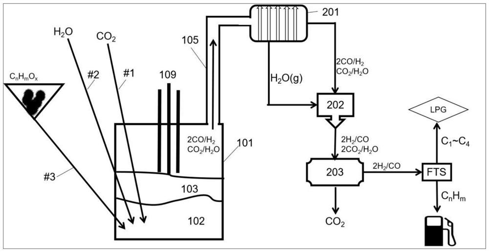
[0087] Set up a set of demonstration devices, the core of which is a closed molten iron gasifier 101 isolated from the outside atmosphere, which contains 60-100 tons of molten iron at a temperature of 1300-1600°C and maintains normal pressure, three Spray guns #1, #2, and #3 are inserted into the gasifier from the top and side walls, and immersed into the molten iron 102. The spray guns are made of refractory materials and can resist the erosion of molten iron for a certain period of time. A small flow of nitrogen gas is continuously injected into the spray gun to prevent the nozzle of the spray gun from being blocked by solidification of molten iron.
[0088] The gasifier is heated by a three-phase AC heating electrode 109 with a heating power of 5000KVA. The electrode hole adopts a dynamic sealing structure commonly used in metallurgy to isolate the atmosphere.
[0089]At the beginning of the demonstration, all spray guns increased the nitrogen flow rate and injected no mate...
Embodiment 2
[0097] The device configuration is the same as in Example 1.
[0098] Lance #1 sprays CO 2 Gas, spray gun #2 sprays liquid water mist carried by nitrogen gas. The injection volumes of carbon dioxide and water mist are both 2000kg / hr, and nitrogen is used as the carrier gas for water spray. The mass ratio of carrier gas nitrogen to water mist is 1:8 to 1:10.
[0099] The high-temperature furnace gas does not count the carrier gas nitrogen, and the hourly output is 3500NM 3 / hr, the composition is H 2 Gas 42%, CO Gas 25%, CO 2 Gas 4%, H 2 O water vapor is 29%.
[0100] After cooling, drying and dehydration, the output of furnace gas excluding nitrogen is 2485NM 3 / hr, the effective gas volume without carbon dioxide is 2345NM 3 / hr, effective gas H 2 The / CO ratio was 1.68.
[0101] After the furnace gas is compressed, it is sent to the steam conversion device 202, and the hydrogen-carbon ratio is adjusted to 2.1-2.3, and then most of the carbon dioxide is removed throu...
Embodiment 3
[0108] Two identical devices in Examples 1-2 were used. The spray gun #1 of the first set of equipment sprays limestone particles, the limestone contains more than 95% calcium carbonate, and the particle size does not exceed 1mm. Nitrogen is used as the carrier gas, and the mass ratio of nitrogen gas to limestone is 1:15.
[0109] The amount of limestone injected per hour is 4000kg / hr, and the composition of the obtained furnace gas is 92% of CO gas, CO 2 Gas 8%, effective synthesis gas per hour, that is, the amount of CO gas is 780NM 3 / hr. After the furnace gas is cooled and dedusted, it is compressed and sent to the steam conversion unit 202. The CaO and iron oxide products FeO and a small amount of Fe after the material decomposition 2 o 3 into the slag phase.
[0110] The second furnace only has spray gun #2 to inject material, and the material is Ca(OH) below 1mm 2 Granular, Ca(OH) 2 Decompose and dehydrate at 580°C, Ca(OH) in molten iron 2 Equivalent to CaO and H...
PUM
 Abstract
Description
Claims
Application Information
 - R&D
- Intellectual Property
- Life Sciences
- Materials
- Tech Scout
- Unparalleled Data Quality
- Higher Quality Content
- 60% Fewer Hallucinations
Browse by: Latest US Patents, China's latest patents, Technical Efficacy Thesaurus, Application Domain, Technology Topic, Popular Technical Reports.
© 2025 PatSnap. All rights reserved.Legal|Privacy policy|Modern Slavery Act Transparency Statement|Sitemap|About US| Contact US: help@patsnap.com


