Adjustable high-frequency electromagnetic band gap band-pass filter

A high-frequency electromagnetic and filter technology, applied to waveguide devices, circuits, electrical components, etc., can solve the problems of low process precision, limited filter application, large filter size, etc., to improve energy storage capacity, structure Simple, the effect of improving the Q value

Active Publication Date: 2022-02-08
JIANGNAN UNIV
View PDF1 Cites 0 Cited by
  • Summary
  • Abstract
  • Description
  • Claims
  • Application Information

AI Technical Summary

Problems solved by technology

[0006] Currently proposed EBG filters are usually realized by simply modifying the periodic structure of the EBG substrate, which limits the application of such filters in a wide frequency range
At the same time, the current EBG is generally processed by the Printed Circuit Board (PCB) process; affected by the low processing precision of the process, this type of filter has the problems of large size and high operating frequency

Method used


Image

  • Adjustable high-frequency electromagnetic band gap band-pass filter
  • Adjustable high-frequency electromagnetic band gap band-pass filter
  • Adjustable high-frequency electromagnetic band gap band-pass filter

Examples


Embodiment 1

[0048] This embodiment provides an adjustable high-frequency electromagnetic bandgap bandpass filter, characterized in that the high-frequency electromagnetic bandgap bandpass filter includes: an EBG resonant cavity and a bottom stack structure;

[0049] The bottom stack structure is located at the bottom of the EBG resonant cavity, and is used to improve the energy storage capacity of the high-frequency electromagnetic bandgap bandpass filter and improve the Q value;

[0050] The EBG resonant cavity contains a capacitor structure, and the resonant frequency of the high-frequency electromagnetic bandgap bandpass filter can be adjusted by adjusting the size of the capacitor plate of the capacitor.

[0051] The high-frequency electromagnetic bandgap filter provided in this embodiment introduces a high-Q capacitor structure into the EBG cavity to greatly reduce the operating frequency of the filter, so that the small-sized EBG structure can also work in the low-frequency band, and...

Embodiment 2

[0054] This embodiment provides an adjustable high-frequency electromagnetic bandgap bandpass filter.

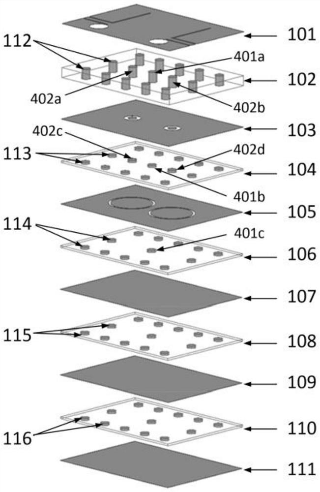
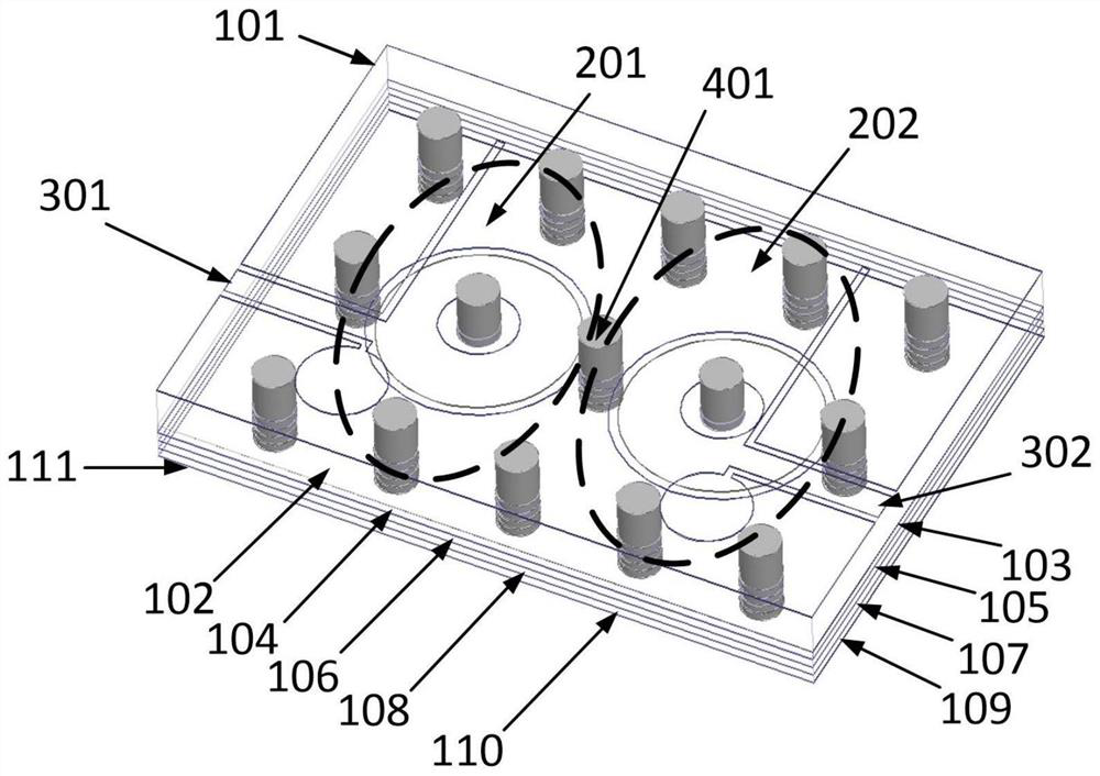
[0055] The structural decomposition of the filter of this embodiment figure 1 As shown, it includes: top layer metal plate 101, first layer dielectric plate 102, second layer through-hole metal plate 103, second layer dielectric plate 104, third layer metal plate 105, third layer dielectric plate 106, fourth layer Metal plate 107, fourth layer of dielectric plate 108, fifth layer of metal plate 109, fifth layer of dielectric plate 110 and sixth layer of bottom metal plate 111;

[0056] The top-layer metal plate 101 and the second-layer through-hole metal plate 103 are connected by a plurality of metallized through-hole arrays 401 with the same height passing through the first-layer dielectric plate 112; the second-layer through-hole metal plate 103 and the third-layer metal plate 105 are connected by a plurality of metallized via arrays 113 with the same height passing thro...

Embodiment 3

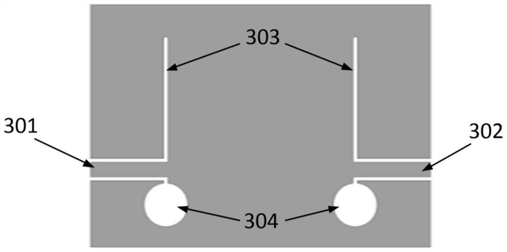
[0067] The difference between the present embodiment and the second embodiment is that, in the present embodiment, the length of the groove line 303 is 1.9mm, the radius of the metal disks 601a and 601b is 0.65mm, and the radius of the hollow circle 304 is 0.5mm. The comparison curve between the parameter simulation and the actual measurement is as follows: Figure 9 as shown in b.


PUM

PropertyMeasurementUnit
lengthaaaaaaaaaa
radiusaaaaaaaaaa
lengthaaaaaaaaaa

Abstract

The invention discloses an adjustable high-frequency electromagnetic band gap band-pass filter, and belongs to the field of microwave / millimeter wave filters. The high-frequency electromagnetic band gap band-pass filter is manufactured by an LTCC process and comprises an EBG resonant cavity and a bottom stacking structure, and a capacitor structure is contained in the EBG resonant cavity. According to the filter, a high-Q-value capacitor structure is introduced into an EBG cavity, so that the working frequency of the filter is greatly reduced, a small-size EBG structure can also work in a low-frequency band, the working frequency can be adjusted by adjusting the size of a capacitor plate, and the relative bandwidth is kept unchanged; by adopting a multi-layer structure, the energy storage capacity of the filter is improved by adding the dielectric plate and the metal plate structure on the bottom layer, and the Q value is improved; in addition, the invention has the advantages of simplicity, adjustability, simple structure, easiness in integration and the like, and can be applied to the future high-frequency field.

Description

technical field [0001] The invention relates to an adjustable high-frequency electromagnetic bandgap bandpass filter, which belongs to the field of microwave / millimeter wave filters. Background technique [0002] With the rapid development of wireless communication technology, modern communication systems have stricter requirements for signal selection. And now the existing spectrum resources are getting tighter and tighter, high operating frequency, wideband outer stop band, and high rectangularity have become the mainstream direction of filter development. Therefore, the development of high-performance millimeter-wave filters has received extensive attention, but millimeter-wave filters based on traditional microstrip lines or waveguide structures generally have problems such as complex structure and large volume, and due to the existence of high-order modes, these two Both types of filters will generate higher harmonics at high frequencies, which will affect out-of-band ...

Claims


Application Information

Patent Timeline
Patent Type & Authority Applications(China)
IPC IPC(8): H01P1/208H01P11/00
CPCH01P1/208H01P11/007
Inventor 郭瑜王浩威沈言霞童星星任鼎新
Owner JIANGNAN UNIV
Why Eureka
Try Eureka