
Device and method for compensating thermal distortion of DPL laser by using hologram generated by SLM

A laser and thermal distortion technology, applied in the field of lasers, can solve problems such as low convergence speed, limited precision, and long response time, and achieve the effects of improving beam quality, reducing costs, and increasing output power

Active Publication Date: 2022-02-08
武汉优科瑞特信息技术有限公司
View PDF4 Cites 0 Cited by
  • Summary
  • Abstract
  • Description
  • Claims
  • Application Information

AI Technical Summary

Problems solved by technology

AO correction technology includes no wavefront detection and wavefront detection. The AO correction technology without wavefront detection is widely used in the beam purification of solid-state lasers because it can be corrected in the resonator and can overcome the limited accuracy of wavefront detection. However, it often requires multiple adjustments to obtain it, and if the convergence speed of the algorithm is low, the correction bandwidth of the AO system without wavefront detection cannot meet the requirements; although the bandwidth of the AO correction technology with wavefront detection is much larger than that without wavefront detection Front-detection AO technology, but due to the use of wavefront detectors, the accuracy of wavefront detection is limited, and the micro-deformable mirror of the corrector is difficult to process, expensive, and has a long response time, and cannot correct tilt and aberration
[0004] Based on the above analysis, there is currently no effective means to solve the thermal distortion of DPL lasers

Method used


Image

  • Device and method for compensating thermal distortion of DPL laser by using hologram generated by SLM
  • Device and method for compensating thermal distortion of DPL laser by using hologram generated by SLM
  • Device and method for compensating thermal distortion of DPL laser by using hologram generated by SLM

Examples


Embodiment Construction

[0023] In order to make the purpose, technical solution and advantages of the present invention clearer, the embodiments of the present invention will be further described below in conjunction with the accompanying drawings.

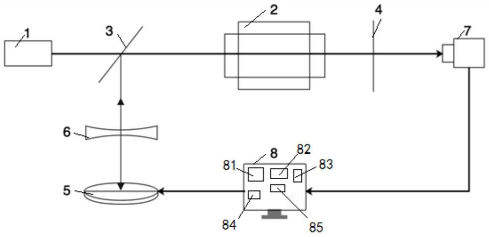
[0024] Please refer to figure 1 , the embodiment of the present invention provides a kind of device that utilizes SLM to produce hologram compensation DPL laser thermal distortion, comprises: laser diode 1, laser 2, high reflection mirror 3, output coupler 4, spatial light modulator (SLM) 5 , beam expander 6, CCD detector 7 and processing device 8.

[0025] The laser diode 1 is used to output the reference light, the laser 2 is used to output the laser light, the high reflective mirror 3 is located between the laser diode 1 and the laser 2, the beam expander 6 is located in the light emitting direction of the high reflective mirror 3, and the spatial light modulator 5 is located In the light-emitting direction of the beam expander 6, the CCD detector 7 ...


PUM


Abstract

The invention relates to the technical field of lasers, in particular to a device and method for compensating thermal distortion of a DPL laser through a hologram generated by an SLM. The device provided by the invention comprises a laser diode, a laser, a high-reflection mirror, an output coupler, a spatial light modulator, a beam expander, a CCD detector and a processing device. The laser diode is used for outputting reference light, the laser is used for outputting laser, the high-reflection mirror is located between the laser diode and the laser, the beam expander is located in the light emitting direction of the high-reflection mirror, and the spatial light modulator is located in the light emitting direction of the beam expander; the CCD detector is used for detecting laser reflected by the spatial light modulator, the output coupler is located between the CCD detector and the laser, the processing device is electrically connected with the CCD detector and the spatial light modulator, and the processing device collects laser spot data output by the CCD detector, and finely adjusts the hologram of the spatial light modulator according to the laser spot data.

Description

technical field [0001] The invention relates to the technical field of lasers, in particular to a device and method for compensating thermal distortion of a DPL laser by using an SLM to generate a hologram. Background technique [0002] Laser diode-pumped solid-state laser (DPL) is a new type of laser that has been widely used in recent years. This type of laser uses a fixed-wavelength semiconductor laser instead of the traditional krypton lamp or xenon lamp to pump the laser crystal. development of. [0003] As the power of the DPL laser increases, its output beam is more and more affected by the "thermal effect", and the beam quality deteriorates rapidly as the power increases, making it difficult to meet the needs of high-power, high-beam quality laser output. In order to overcome the influence of thermal distortion on the performance of DPL lasers, researchers use phase conjugate mirrors and diffractive optical devices to reduce thermal distortion. This method is compli...

Claims


Application Information

Patent Timeline
Patent Type & Authority Applications(China)
IPC IPC(8): H01S3/13G03H1/22
CPCH01S3/1305G03H1/2294Y02P10/25
Inventor 周晶程其娈金张程思毅
Owner 武汉优科瑞特信息技术有限公司
Learn More