
Method and device for treating tail gas by adopting excimer light source technology

A technical treatment, excimer technology, applied in the field of exhaust gas treatment using excimer light source technology, can solve problems such as energy loss, side reactions, human harm, etc., to improve the efficiency of sterilization, delay residence time, and reduce hazardous waste emissions. Effect

Pending Publication Date: 2022-02-11
HWASU
View PDF12 Cites 0 Cited by
  • Summary
  • Abstract
  • Description
  • Claims
  • Application Information

AI Technical Summary

Problems solved by technology

[0004] When waste sulfuric acid reacts with calcium carbide slag, the high reaction temperature will bring about uncertain side reactions, resulting in foul smell in the tail gas. Under the current environmental protection pressure, this bad smell seriously restricts the operation of the by-product gypsum
If the tail gas is discharged into the air without treatment, it will pollute the environment and cause harm to the human body. The existing tail gas treatment devices have the following problems: (1) lack of heat recovery device, due to the reaction process of waste sulfuric acid and calcium carbide slag will produce a large amount of Heat, which is taken away by the tail gas, resulting in energy loss; (2) The cost of tail gas purification is high, and the raw materials for tail gas treatment cannot be recycled

Method used


Image

  • Method and device for treating tail gas by adopting excimer light source technology
  • Method and device for treating tail gas by adopting excimer light source technology

Examples


Embodiment Construction

[0024] The present invention will be further explained below in conjunction with the accompanying drawings and specific embodiments. It should be understood that the following specific embodiments are only used to illustrate the present invention and are not intended to limit the scope of the present invention. It should be noted that the words "front", "rear", "left", "right", "upper" and "lower" used in the following description refer to the directions in the drawings, and the words "inner" and "outer ” refer to directions towards or away from the geometric center of a particular part, respectively.

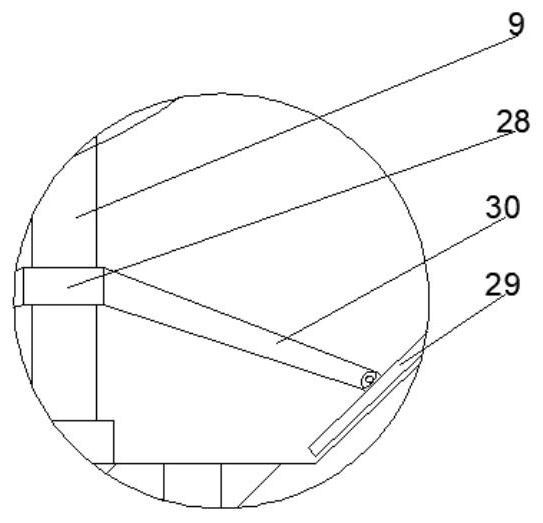
[0025] Such as Figure 1-2 Shown is a method and device for treating exhaust gas using excimer light source technology. The device includes a stirring mechanism 1, a gypsum production plant 2, a heat exchange mechanism 3, a spray absorption tower 4, and an ultraviolet sterilizing box 5 arranged in sequence from left to right , a water washing tower 6, the left side of the gyps...


PUM


Abstract

The invention discloses a method and a device for treating tail gas by adopting an excimer light source technology. The device comprises a stirring mechanism, a gypsum production plant, a heat exchange mechanism, a spray absorption tower, an ultraviolet sterilization box and a water scrubber which are sequentially arranged from left to right, then dilute sulphuric acid and carbide slag are put into a stirring tank to generate a neutralization reaction, and when a byproduct gypsum is obtained, in the production process, tail gas can enter a heat exchange inner pipeline; the tail gas entering the heat exchange inner pipeline collides with a superconducting heat exchange pipe to exchange heat; the tail gas discharged from the heat exchange inner pipeline enters a spraying absorption tower, solid impurities and dust in the tail gas are absorbed, and meanwhile, the tail gas reacts with spraying alkaline liquid and has a neutralization reaction with acidic substances in the tail gas; and the tail gas discharged from the spray absorption tower enters the ultraviolet sterilization box and then is discharged through the water scrubber. The method and device for treating tail gas have the beneficial effects that the tail gas can be thoroughly purified, heat in the tail gas is recycled, and the tail gas treatment cost is reduced.

Description

technical field [0001] The invention belongs to the technical field of tail gas treatment, and in particular relates to a method and a device for treating tail gas using excimer light source technology. Background technique [0002] Acetylene gas is produced by dry acetylene process using calcium carbide as raw material. Concentrated sulfuric acid is used to clean the acetylene gas during the production process. After 98% of the concentrated sulfuric acid is cleaned and the concentration is lower than 80%, it needs to be discharged from the device, and a large amount of waste sulfuric acid is produced every year. This waste sulfuric acid contains various impurities such as hydrocarbon carbides, elemental sulfur, sulfurous acid, sulfuric acid and phosphoric acid. [0003] At present, the treatment technology of industrial waste sulfuric acid utilizes the principle of acid-base neutralization, and neutralizes waste sulfuric acid with alkaline neutralizers such as lime. This m...

Claims


Application Information

Patent Timeline
Patent Type & Authority Applications(China)
IPC IPC(8): B01D53/78B01D53/96B01D53/40B01D53/18B01D53/00B01D47/06B01J19/18B01D29/56B01D29/03A61L9/20C01F11/46F28D7/10F28D15/00
CPCB01D53/78B01D53/40B01D53/007B01D47/06B01D53/96B01D53/18B01D29/56B01D29/03A61L9/20B01J19/18B01J19/0053B01J19/0066C01F11/46F28D7/10F28D15/00B01D2259/804B01D2257/91
Inventor 魏昭晖卢鑫
Owner HWASU
Learn More