
Intelligent laser welding treatment method for stainless steel

A technology of laser welding and processing methods, which is applied in the direction of laser welding equipment, welding equipment, metal processing equipment, etc., can solve the problems of inability to adjust the welding track, complicated operation, and low welding accuracy, and achieve the elimination of human factors. High, guaranteed accuracy effect

Pending Publication Date: 2022-02-15
JILIN UNIV
View PDF0 Cites 0 Cited by
  • Summary
  • Abstract
  • Description
  • Claims
  • Application Information

AI Technical Summary

Problems solved by technology

[0003] The main method of stainless steel welding is laser welding. Robotic laser welding has significant advantages such as high production efficiency, high energy density, and small deformation after welding. It generally requires manual teaching before welding to determine the welding trajectory. Complicated, and also affected by human factors, the welding accuracy is low, and the welding trajectory cannot be adjusted in real time for different welds, which cannot meet the needs of high-precision welding and efficient welding
[0004] In recent years, laser seam tracking technology and arc tracking technology have emerged, both of which can correct the welding trajectory of welding methods such as robot or automation equipment tungsten argon arc welding and gas metal arc welding in real time, ensuring high welding accuracy; However, for stainless steel laser welding, due to the high reflective performance of stainless steel, narrow gap (<1mm) welding, and dense laser beams, etc., laser seam tracking technology and arc tracking technology are difficult to apply to real-time deviation correction of stainless steel laser welding trajectory

Method used


Image

  • Intelligent laser welding treatment method for stainless steel
  • Intelligent laser welding treatment method for stainless steel
  • Intelligent laser welding treatment method for stainless steel

Examples


Embodiment 1

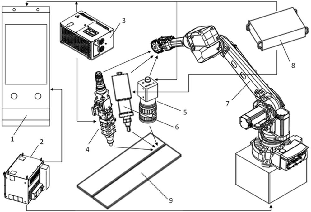
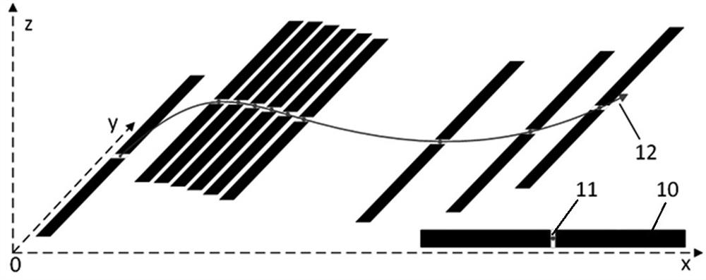
[0043] like figure 1 and figure 2 As shown, a stainless steel intelligent laser welding processing method comprises the following steps:

[0044] Step S1. According to the established teaching track and the established shooting frame rate, use the CDD industrial camera 5 to continuously capture images of the stainless steel butt joint gap to obtain the image data stream. During the shooting process, the optical axis of the CDD industrial camera 5 should be as perpendicular to the stainless steel as possible The plane where the parent material is located.

[0045]Step S2. Set the ROI image area of ​​each frame of pictures as (u1, v1, size.width, size.height), where (u1, v1) represents the pixel vertex coordinates of the ROI image area, and size.width represents the size of the ROI image area Width, size.height indicates the height of the ROI image area; the ROI image area is converted to grayscale and smoothed, and the method of smoothing is two consecutive median filters, a...

Embodiment 2

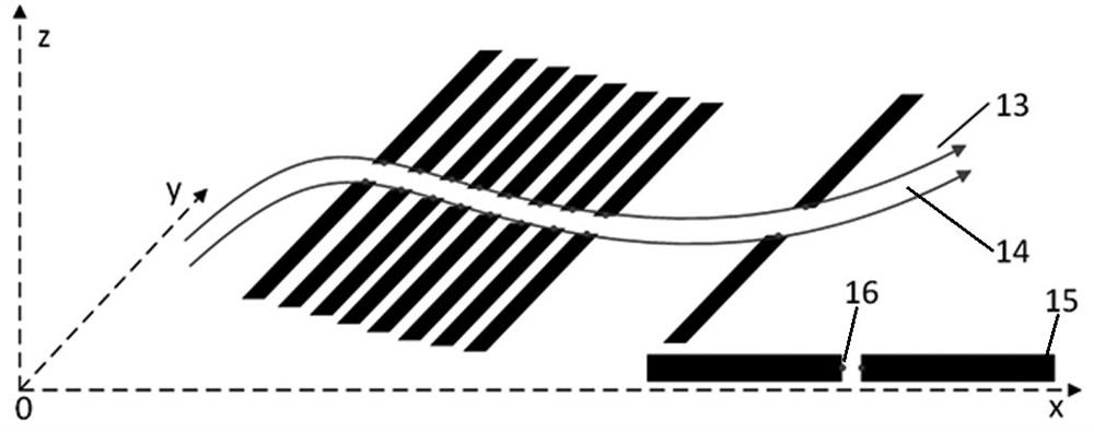
[0066] like figure 1 , image 3 and Figure 4 As shown, the difference between this embodiment and Embodiment 1 is that the stainless steel intelligent laser welding treatment method further includes a subsequent post-processing operation of performing intelligent ultrasonic impact on the stainless steel weld seam.

[0067] The stainless steel weld is subjected to an intelligent ultrasonic impact method, which specifically includes the following steps:

[0068] (1) According to the method of steps S1-S4, scan and image process the stainless steel weld after welding, and finally obtain an image in which the stainless steel weld is represented by white and the stainless steel base material is represented by black—the stainless steel weld after morphological trimming ROI image15.

[0069] (2) Extract the pixel coordinates of the midpoints of the two edges of the white area of ​​each frame of the post-welding ROI image (white area edge 16), and convert the pixel coordinates of ...


PUM


Abstract

The invention provides an intelligent laser welding treatment method for stainless steel. The method comprises the following steps of picture scanning, ROI setting, gray level conversion, smoothing treatment, adaptive image threshold segmentation, morphological finishing, welding track solving, optical fiber laser pose solving and automatic welding controlled by a laser welding robot. The intelligent laser welding treatment method for stainless steel has the advantages of convenience in operation, automatic welding identification, automatic track generation and high welding precision.

Description

technical field [0001] The invention relates to the field of robot welding, in particular to an intelligent laser welding treatment method for stainless steel. Background technique [0002] Stainless steel, especially ferritic stainless steel, has the advantages of low price, good high temperature resistance, and excellent corrosion resistance, so it is widely used in various occasions in the field of welding, such as cold bending of automobile exhaust pipes, expansion forming, and stainless steel for car bodies. Sheet metal welding, etc. [0003] The main method of stainless steel welding is laser welding. Robotic laser welding has significant advantages such as high production efficiency, high energy density, and small deformation after welding. It generally requires manual teaching before welding to determine the welding trajectory. It is complicated, and it is also affected by human factors, which leads to low welding accuracy, and the welding trajectory cannot be adjus...

Claims


Application Information

Patent Timeline
Patent Type & Authority Applications(China)
IPC IPC(8): B23K26/21B23K26/03B23K26/70
CPCB23K26/21B23K26/032B23K26/702Y02P90/30
Inventor 赵小辉王浩刘宇徐德生蒋豪徐龙哲
Owner JILIN UNIV
Learn More