
Foamed aluminum pole piece coating equipment and pole piece manufacturing method applying same

A technology of coating equipment and aluminum foam, which is applied to the surface coating liquid device, coating, hybrid capacitor electrodes, etc., can solve the uneven thickness of the slurry on both sides of the pole piece, which affects the yield of the pole piece and production cost Advanced problems, to achieve the effect of improving coating adequacy and uniformity, accurately controlling the thickness of the pole piece, and increasing the filling rate

Active Publication Date: 2022-02-15
ZHONGTIAN SUPERCAPACITOR TECH CO LTD +1
View PDF6 Cites 1 Cited by
  • Summary
  • Abstract
  • Description
  • Claims
  • Application Information

AI Technical Summary

Problems solved by technology

This process is suitable for continuous winding aluminum foil, but if the three-dimensional through-hole foamed aluminum adopts this process, the coating slurry will pass through the foamed aluminum to cause a large amount of material leakage during the coating process, resulting in waste of materials and high production costs; and, The aluminum foam pole piece has a three-dimensional structure, and the slurry needs to be evenly filled in the three-dimensional structure. Single-sided extrusion coating will cause uneven thickness of the slurry on both sides of the pole piece, which will affect the yield of the pole piece

Method used


Image

  • Foamed aluminum pole piece coating equipment and pole piece manufacturing method applying same
  • Foamed aluminum pole piece coating equipment and pole piece manufacturing method applying same
  • Foamed aluminum pole piece coating equipment and pole piece manufacturing method applying same

Examples


Embodiment Construction

[0064]The following description will refer to the accompanying drawings to more fully describe the contents of the present application. Exemplary embodiments of the application are shown in the drawings. This application may, however, be embodied in many different forms and should not be construed as limited to the exemplary embodiments set forth herein. Rather, these exemplary embodiments are provided so that this application will be thorough and complete, and will fully convey the scope of this application to those skilled in the art. Like reference numerals designate the same or similar components.

[0065] The terminology used herein is for the purpose of describing particular exemplary embodiments only and is not intended to limit the application. As used herein, the singular forms "a", "an" and "the" are intended to include the plural forms as well, unless the context clearly dictates otherwise. Furthermore, when used herein, "comprises" and / or "comprises" and / or "has...


PUM

PropertyMeasurementUnit
heightaaaaaaaaaa

Abstract

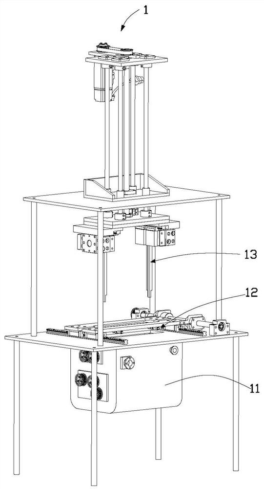
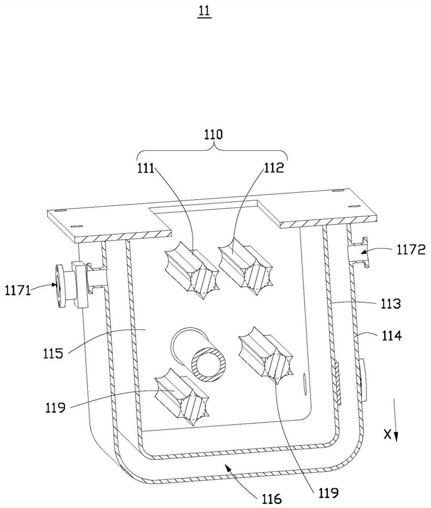
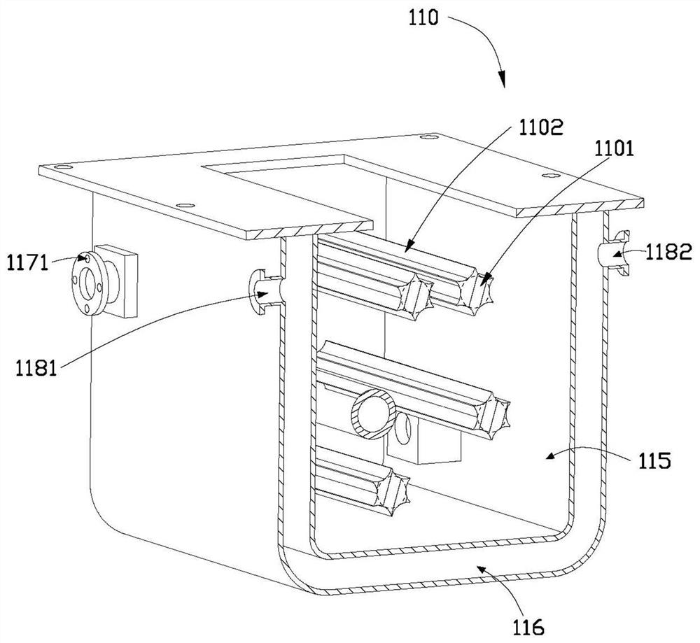
The invention provides foamed aluminum pole piece coating equipment and a pole piece manufacturing method applying same. The foamed aluminum pole piece coating equipment comprises a slurry pool, the slurry pool comprising an extrusion roller, a first cavity being formed in the slurry pool, the extrusion roller being arranged in the first cavity containing slurry, the extrusion roller comprising a roller and blades connected with the roller, the blades protruding towards the outer side of the roller, and the extrusion roller being used for enabling the blades to guide the slurry to a foamed aluminum pole piece through rotation; a scraping plate mechanism, comprising a first scraping plate and a second scraping plate which are arranged at an interval, comb-shaped tooth structures being arranged on the first scraping plate and the second scraping plate, and the comb-shaped tooth structures being used for scraping part of slurry on the surface of the foamed aluminum; a driving mechanism, arranged on the side, away from the slurry pool, of the scraper mechanism and used for driving the foamed aluminum pole piece to move relative to the scraper mechanism and the slurry pool. The foamed aluminum pole piece coating equipment can ensure that slurry in foamed aluminum is filled compactly, and can also achieve the effects of automatic coating, redundant slurry scraping, standing for drying, accurate pole piece thickness control and the like.

Description

technical field [0001] The present application relates to the field of new energy, in particular to a foamed aluminum pole piece coating equipment and a pole piece production method using the same. Background technique [0002] The capacitive carbon carrier material used in mainstream supercapacitors is aluminum foil. However, due to the limitation of the coating thickness of the aluminum foil and the amount of carbon loaded on the aluminum foil, the bottleneck of the voltage window of the supercapacitor cannot be broken through. Therefore, the three-dimensional porous current collector has become a new development research trend in the industry. However, the foamed aluminum three-dimensional current collector is different from the conventional aluminum foil coating method. Its tension and winding performance are far inferior to aluminum foil, and the permeability of the coating And uniformity requirements are high, and the conventional aluminum foil coating method cannot b...

Claims


Application Information

Patent Timeline
Patent Type & Authority Applications(China)
IPC IPC(8): H01G11/86H01G11/68H01G11/32B05C3/09B05C11/02B05C13/02
CPCH01G11/86H01G11/68H01G11/32B05C3/09B05C13/02B05C11/023
Inventor 徐飞飞张刚张帆胡磊严高飞
Owner ZHONGTIAN SUPERCAPACITOR TECH CO LTD
Learn More