PLD (pulsed laser deposition) system provided with hollow cathode plasma and preparation method of thin film

A plasma and hollow cathode technology, applied in the field of thin film transistors, can solve the problems that the performance of ITO thin films cannot meet the requirements

Active Publication Date: 2022-02-18
XI AN JIAOTONG UNIV +1
View PDF15 Cites 0 Cited by
  • Summary
  • Abstract
  • Description
  • Claims
  • Application Information

AI Technical Summary

Problems solved by technology

To solve the problem that the performance of the ITO thin film p

Method used


Image

  • PLD (pulsed laser deposition) system provided with hollow cathode plasma and preparation method of thin film
  • PLD (pulsed laser deposition) system provided with hollow cathode plasma and preparation method of thin film
  • PLD (pulsed laser deposition) system provided with hollow cathode plasma and preparation method of thin film

Examples


preparation example Construction

[0030] The invention also discloses a method for preparing an amorphous ITO thin film of a PLD system with a hollow cathode plasma, the preparation method comprising the following steps:

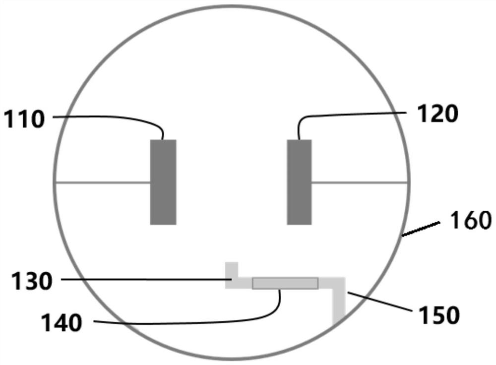
[0031] Step 1, providing and installing a deposition substrate 110;

[0032] Step 2, start the pulsed laser deposition to prepare the amorphous ITO thin film. During the deposition process, the pulsed laser power is 400mJ, the laser frequency is 1Hz, and the distance between the target and the substrate is 70mm. The thickness of the ITO film is about 20nm, the growth rate of the ITO film is 0.8-1nm / pulse, and the amorphous ITO film is deposited in a single-point manner.

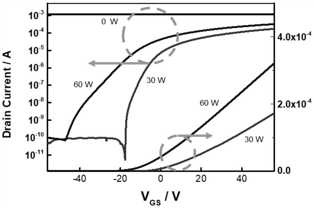
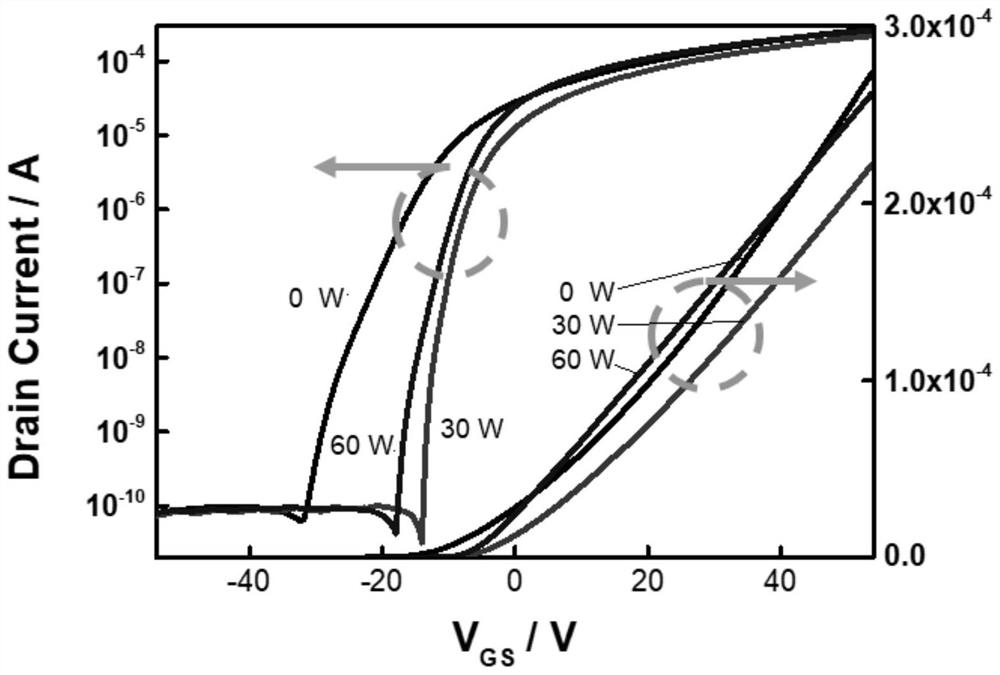
[0033] During the deposition process, the hollow cathode plasma discharge device is turned on, and the background pressure is less than 5×10 -5 Pa, oxygen is used as the working gas, the gas pressure is 3.5-4Pa, the ionization voltage and current are less than 50mA, and the ionization power is less than 60W.

Embodiment 1

[0036] The present embodiment provides a kind of method utilizing hollow cathode discharge plasma assisted PLD to prepare ITO film, and it comprises the following steps:

[0037] (1) Provide deposition substrates (including but not limited to Si / SiO2);

[0038] (2) Utilize hollow cathode discharge plasma-assisted PLD to prepare ITO film on described substrate;

[0039] In step (2), the ITO film is prepared by pulsed laser deposition, the thickness of the ITO film is about 20 nm, and the growth rate of the ITO film is 0.8-1 nm / pulse.

[0040] In step (2), the hollow cathode discharge plasma assisted PLD is used to prepare the ITO film on the substrate, the ionization voltage is 1.5kV, the ionization current is 20mA, and the vacuum degree is lower than "5×"〖"10"〗^ "-5"Pa, through O 2 As the working gas, the gas pressure is 3.5Pa, the laser power is 400mJ, and the substrate temperature is room temperature.

Embodiment 2

[0042]The difference between this embodiment and Embodiment 1 is that the ionization voltage of the hollow cathode discharge plasma is 2.0 kV, and the ionization current is 30 mA. Other operating steps and parameters are all the same as in Example 1.


PUM

PropertyMeasurementUnit
Thicknessaaaaaaaaaa

Abstract

The invention discloses a PLD system provided with hollow cathode plasma and a preparation method of a thin film. The system is provided with a plasma discharge system in a vacuum cavity of an existing PLD system; and only the middle part of a gas path stainless steel pipe in the existing PLD system is replaced by an aluminum oxide insulating ceramic pipe, one end of the pipe is connected with a power supply, and the other end of the pipe is connected with a gas circuit, so a discharge device is formed. According to the device, negative glow regions of oxygen plasmas can be overlapped, the collision frequency of electrons and gas atoms is increased, ionization effect is remarkably improved, the concentration of the oxygen plasmas in a pulse laser deposition cavity is effectively improved, the content of oxygen vacancies in an ITO thin film is reduced, the problem that the threshold voltage of an amorphous ITO thin film transistor is slightly negative is solved, the subthreshold swing and mobility of the device are optimized to a certain extent, and the performance of the thin film transistor is improved.

Description

technical field [0001] The invention belongs to the technical field of thin film transistors, and in particular relates to a PLD system with hollow cathode plasma and a thin film preparation method. Background technique [0002] Thin film transistors are one of the core devices in the field of display technology, and metal oxide semiconductor materials have great application potential in the next generation of thin film transistor applications. ITO is one of its representatives. Amorphous ITO films usually have more oxygen defects and exhibit good conductivity, but good conductivity will make amorphous ITO films used as channel layers in thin film transistors, resulting in low device turn-on voltage and poor switching ratio. Therefore, reducing the content of oxygen defects is an important way to improve the performance of amorphous ITO thin film transistors. In the process of pulsed laser deposition, feeding oxygen into the cavity can reduce the concentration of oxygen de...

Claims


Application Information

Patent Timeline
IPC IPC(8): C23C14/28C23C14/08C23C14/54
CPCC23C14/28C23C14/086C23C14/0021C23C14/54
Inventor 马飞路文墨王琛李奉南
Owner XI AN JIAOTONG UNIV
Why Eureka
Try Eureka