
LED chip and manufacturing method thereof

A technology for LED chips and manufacturing methods, applied in semiconductor devices, electrical components, circuits, etc., can solve problems such as affecting the luminous intensity of LED chips, and achieve the effects of improving LED luminous efficiency, simplifying the wiring process, and eliminating adverse effects.

Pending Publication Date: 2022-02-18
JUCAN PHOTOELECTRIC TECH (SUQIAN) CO LTD
View PDF3 Cites 0 Cited by
  • Summary
  • Abstract
  • Description
  • Claims
  • Application Information

AI Technical Summary

Problems solved by technology

[0003] However, if the electrodes are placed on the front side of the LED chip, the electrodes will cover a part of the light-emitting area, thereby affecting the luminous intensity of the LED chip.

Method used


Image

  • LED chip and manufacturing method thereof
  • LED chip and manufacturing method thereof
  • LED chip and manufacturing method thereof

Examples


Embodiment Construction

[0037] In order to make the purpose, technical solution and advantages of the present application clearer, the following will clearly and completely describe the technical solution of the present application in combination with specific implementation methods of the present application and corresponding drawings. Apparently, the described implementations are only some of the implementations of this application, not all of them. Based on the implementation manners in this application, all other implementation manners obtained by persons of ordinary skill in the art without making creative efforts belong to the scope of protection of this application.

[0038] Embodiments of the present invention are described in detail below, and examples of the embodiments are shown in the drawings, wherein the same or similar reference numerals denote the same or similar elements or elements having the same or similar functions throughout. The embodiments described below by referring to the f...


PUM


Abstract

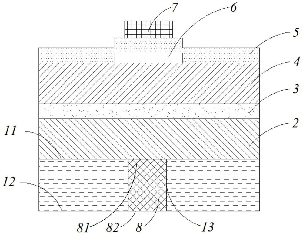
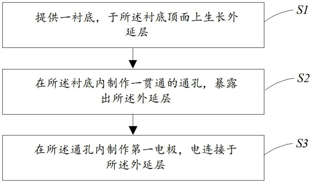
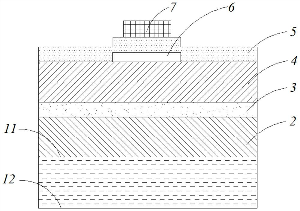
The invention provides an LED chip which comprises a substrate and an epitaxial layer arranged on the substrate, the substrate is provided with a top surface and a bottom surface which are opposite to each other, the top surface is connected with the epitaxial layer, a through hole communicated with the top surface and the bottom surface is formed in the substrate, and the epitaxial layer is exposed in the through hole; and a first electrode is arranged in the through hole and provided with a first end face and a second end face which are opposite, and the first end face is electrically connected with the epitaxial layer. By arranging the first electrode in the substrate and electrically connecting the first electrode with the epitaxial layer, the first electrode can be located on the back face of the epitaxial layer, on one hand, the adverse effect of the first electrode originally covering the front face of the LED chip on the light-emitting area can be eliminated, and the LED light-emitting efficiency is improved; and on the other hand, the front surface of the LED chip is only provided with the single second electrode, so that the routing process during packaging of the LED chip can be effectively simplified, and the first electrode is electrically connected with the substrate through the conductive adhesive or in other modes, so that the problems of poor contact, wire breakage and the like of electric welding wiring can be effectively reduced, and the yield of the LED chip is improved.

Description

technical field [0001] The invention relates to the field of semiconductor light emitting devices, in particular to the LED chip and a manufacturing method thereof. Background technique [0002] Light Emitting Diode (English: Light Emitting Diode, referred to as: LED), as a new type of energy-saving and environmentally friendly solid-state lighting source, has the advantages of high energy efficiency, small size, light weight, fast response and long life, making it widely used in many fields. widely used. LED front-mount chip is the earliest chip structure, and it is also a chip structure commonly used in low-power chips. Since the non-conductive sapphire substrate is generally used for front-mounted LED chips, in this structure, the second electrode and the first electrode are respectively located above the P-type semiconductor layer and the N-type semiconductor layer to realize electrical connection. [0003] However, if the electrodes are arranged on the front side of t...

Claims


Application Information

Patent Timeline
IPC IPC(8): H01L33/38H01L33/20H01L33/00
CPCH01L33/38H01L33/20H01L33/0075H01L2933/0016
Inventor 不公告发明人
Owner JUCAN PHOTOELECTRIC TECH (SUQIAN) CO LTD
Learn More