

Multi-chip packaging structure applied to dynamic backlight
A technology of multi-chip packaging and dynamic backlight, which is applied to semiconductor devices of light-emitting elements, cooling/heating devices of lighting devices, light sources, etc., can solve the problems of affecting light emission, heat cannot be quickly dissipated outward, and shortening lifespan, etc. Achieve the effect of accelerating heat dissipation efficiency, improving electro-optical conversion efficiency, and improving light output efficiency
- Summary
- Abstract
- Description
- Claims
- Application Information
AI Technical Summary
Problems solved by technology
Method used
Image

Examples
Embodiment 1
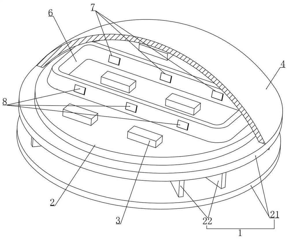
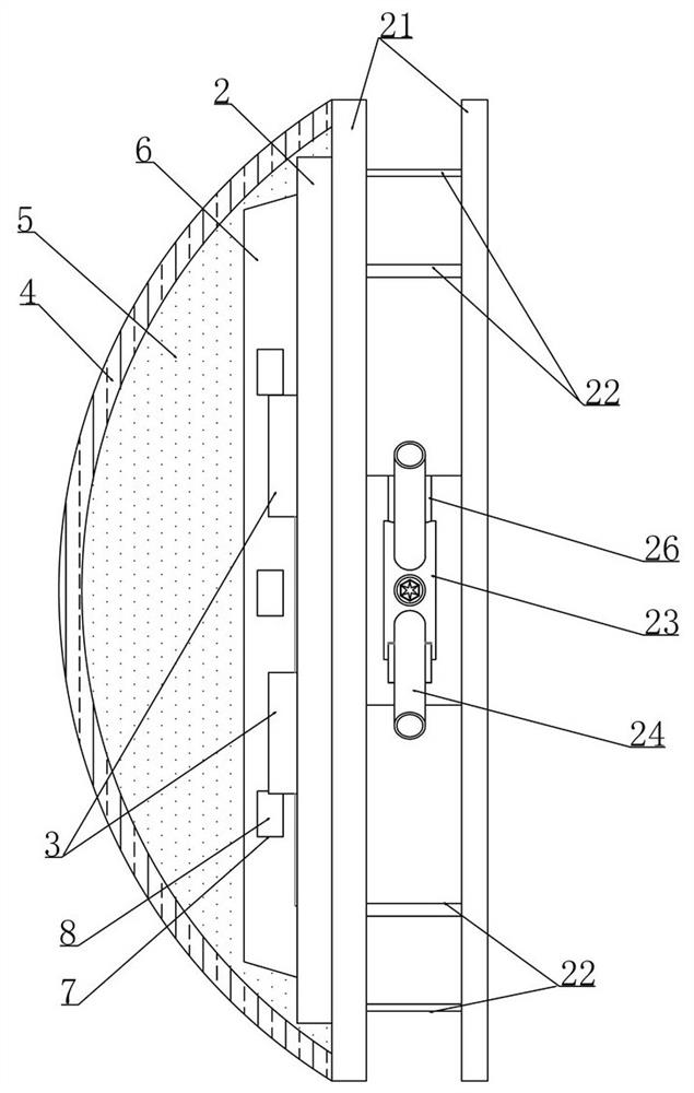
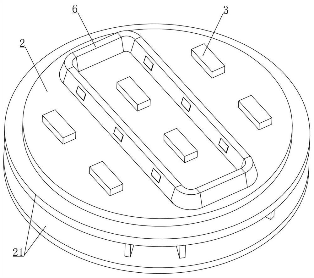
[0028] Embodiment 1, a multi-chip packaging structure applied to dynamic backlight, as attached figure 1 As shown, the heat dissipation base 1 is provided with an insulating layer 2 and the LED chip 3 is installed on the insulating layer 2 to achieve a better insulation effect and prevent the LED chip 3 from being damaged due to leakage or short circuit. The lens 4 and the encapsulation lens 4 are filled with encapsulation glue 5 (silica gel). While providing better physical protection effect for the LED chip 3, in order to achieve a better light output effect for the LED chip 3, the improvement of this solution lies in: as attached figure 2 As shown, the insulating layer 2 is installed with a closed channel 6 between several LED chips 3, and the encapsulation glue 5 also wraps the closed channel 6 (the closed channel 6 is in close contact with the encapsulant 5), and the multi-LED chip 3 is packaged. At this time, the light generated by the LED chip 3 will be emitted outwar...
Embodiment 2
[0035] Embodiment 2, on the basis of embodiment 1, as attached Figure 7 As shown, the corresponding two blocking plates 8 are fixedly connected through the connecting rod 12, and the transmission device includes a long swing rod 13 that is rotatably installed with the center of the connecting rod 12. When the temperature in the closed passage 6 exceeds the required range, the sensor The temperature device drives the short swing rod 16 which is rotated and installed with it to move and then realizes the rotation of the small circular plate 15 which is eccentrically rotated and installed with the short swing rod 16, and the rotation of the small circular plate 15 then drives the large circular plate 14 which rotates coaxially with it. Rotation (the cooperation of the small circular plate 15 and the large circular plate 14 achieves the effect of enlarging the stroke), accompanied by the rotation of the large circular plate 14, and then the long swing rod 13 installed eccentricall...
Embodiment 3
[0037] Embodiment 3, on the basis of embodiment 2, as attached Figure 7 As shown, the temperature sensing device includes a temperature sensing block 17 fixedly installed on the top wall of the closed channel 6, and the temperature sensing block 17 is made of a material that is easy to expand when heated, such as a thermal bimetal, etc., when it is heated, it will expand to a certain extent, Deformation, which in turn will produce a certain distance of motion;
[0038] Thermal bimetal refers to a composite material that is firmly bonded together by two (or more) metal or alloy component layers with different thermal expansion coefficients. According to the different materials used first, different types of thermal bimetal can be finally obtained. Metals, such as high-temperature type, medium-temperature type, low-temperature type, high-sensitivity type, etc., can cause a certain degree of expansion and deformation for temperature changes in different temperature ranges;
[0...
PUM
 Abstract
Description
Claims
Application Information