Integrated slurry pump and manufacturing mold thereof

A technology for slurry pumps and molds, applied to pumps for special fluids, parts of pumping devices for elastic fluids, pumps, etc., can solve problems such as difficult assembly, complex structure, and difficulty in ensuring sealing performance, and achieve improved sealing High performance, high strength and good sealing performance

Pending Publication Date: 2022-02-25
HANJIANG HONGYUAN XIANGYANG SILICON CARBIDE SPECIAL CERAMICS
View PDF1 Cites 1 Cited by
  • Summary
  • Abstract
  • Description
  • Claims
  • Application Information

AI Technical Summary

Problems solved by technology

The slurry pump guarantees the sealing of the pump body by setting various mechanical structures, the structure is complicated, the assembly is difficult, and the sealing is difficult to guarantee after a long service life

Method used


Image

  • Integrated slurry pump and manufacturing mold thereof
  • Integrated slurry pump and manufacturing mold thereof
  • Integrated slurry pump and manufacturing mold thereof

Examples


Embodiment 1

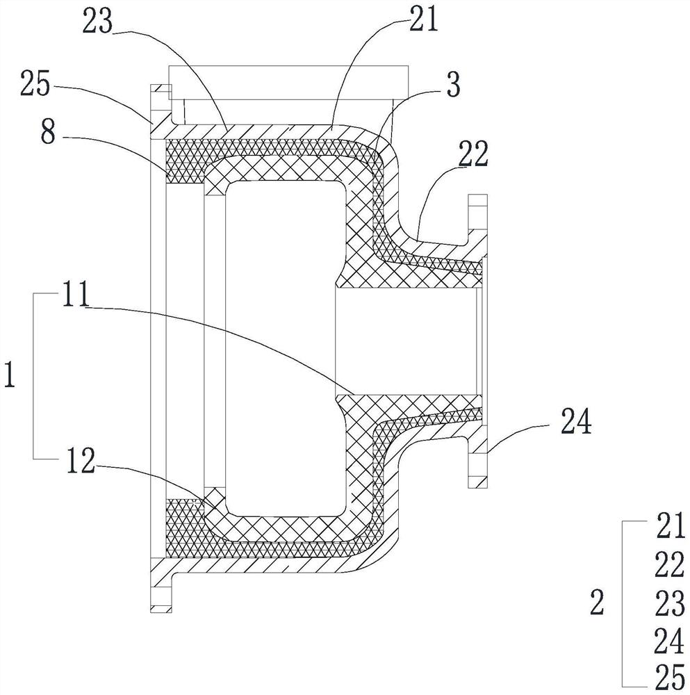
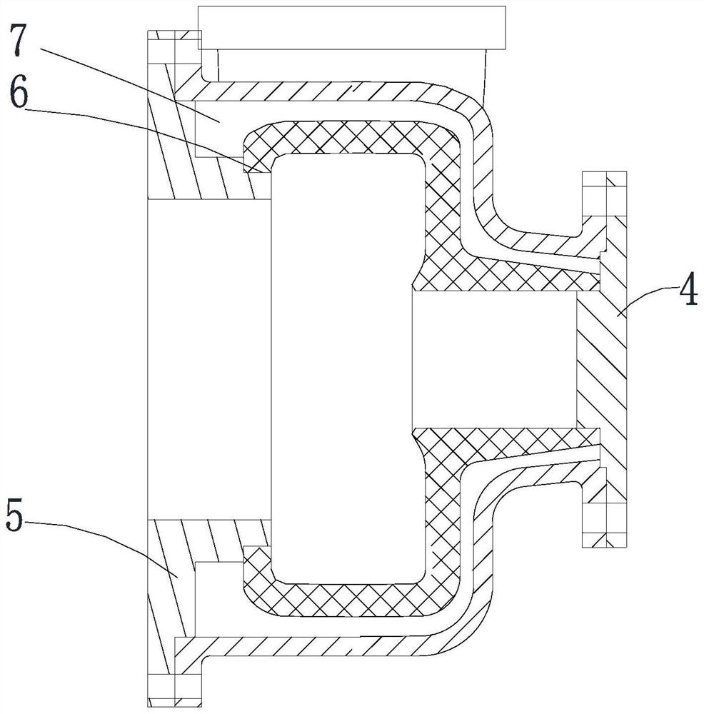
[0028] Integrated slurry pump, such as figure 1 As shown, it includes a volute 1 and a pump casing 2. The pump casing 2 includes a cylindrical pump body 21. The diameter of one side of the pump body 21 shrinks toward the axial direction to form a suction port 22, and the other side is provided with a connection port 23. The diameter of the connection port 23 is The diameter of the main body 21 of the pump is the same, and the size of the connection port 23 allows the volute 1 to be embedded in the pump casing 2. A volute suction port 11 is provided on one side of the volute 1, and the volute suction port 11 is embedded in the suction port 22 of the pump casing 1. , A sealed cavity is provided between the volute 1 and the pump casing 2, and the sealed cavity is filled with an organic-inorganic composite ceramic layer 3, and the constriction portion 12 is set on the side of the volute 1 close to the connection port 23 of the pump casing 2. The suction port 22 of the pump casing ...

Embodiment 2

[0036] The difference between Example 2 and Example 1 is that the resin silicon carbide sand layer consists of 8 parts by mass of modified epoxy resin, 3 parts of coupling agent, 1 part of curing agent diethylenetriamine, and 100 parts of silicon carbide sand. The modified epoxy resin is prepared by reacting 8 parts of epoxy resin, 0.5 part of terephthalic acid and 0.2 part of tetrabutylammonium fluoride. The preparation method is as follows:

[0037] Get 8 parts of epoxy resins and dissolve with n-butanol, join in the four-necked flask that thermometer, stirrer, condenser are housed, add and account for the benzoyl peroxide of 0.5% epoxy resin massfraction again as initiator, Under the protection of nitrogen, raise the temperature of the system to 90-100°C, and slowly add 0.5 parts of terephthalic acid into the system dropwise. After 4 hours of constant temperature reaction, 0.1 part of tetrabutylammonium fluoride was added to the system, the constant temperature reaction wa...


PUM

PropertyMeasurementUnit
Diameteraaaaaaaaaa
Lengthaaaaaaaaaa

Abstract

The invention relates to the technical field of slurry pumps, and discloses an integrated slurry pump and a manufacturing mold thereof. The integrated slurry pump comprises a volute and a pump shell, the pump shell is integrally formed and comprises a pump body, the diameter of one side of the pump body shrinks in the axis direction to form a suction inlet, and a connecting opening is formed in the other side of the pump body; and the volute can be embedded into the pump shell through the connecting opening, a sealed cavity is formed between the volute and the pump shell, and the sealed cavity is filled with a resin silicon carbide sand layer. The slurry pump has the following advantages and effects that the pump shell is integrally formed, splicing of two pump shells is not needed, the sealing performance is good, the volute can be embedded into the pump shell from the connecting opening in the pump shell, then the gap between the pump shell and the volute is filled with the resin silicon carbide sand layer, the volute and the pump shell are bonded, and the integrated slurry pump can be obtained.

Description

technical field [0001] The invention relates to the technical field of slurry pumps, in particular to an integrated slurry pump and a manufacturing mold thereof. Background technique [0002] The slurry pump is composed of impeller, volute, pump casing, guard plate and other components. The pump casing is usually spliced ​​by two metal casings. The two pump casings are connected by bolts to form a closed cavity. The volute and The impeller is located in the cavity, and the sealing of the pump casing is poor. When using a slurry pump to transport corrosive materials, poor sealing will cause the liquid in the volute to leak out of the pump casing, resulting in corrosion of the pump casing. [0003] The Chinese invention patent with the authorized notification number CN110630510B discloses a horizontal slurry pump, which includes a bracket, a bearing assembly horizontally connected to the bracket, a drive shaft installed on the bearing assembly, a pump body fixedly connected t...

Claims


Application Information

Patent Timeline
IPC IPC(8): F04D7/04F04D29/42F04D29/02F04D29/08C08F283/10C08F222/14C08F122/02C04B26/14B29C39/26B29C39/10
CPCF04D7/04F04D29/426F04D29/4286F04D29/4273F04D29/026F04D29/086C08F283/10C08F122/02C04B26/14B29C39/26B29C39/10F05D2300/30F05D2300/44C08F222/14C04B14/324C04B24/121C04B2103/0068
Inventor 李再勇李秋南刘凯陈敬张升玥贾俊杜金辉姜晓灵许斌黄涛刘美童捷程佩王金灿
Owner HANJIANG HONGYUAN XIANGYANG SILICON CARBIDE SPECIAL CERAMICS
Why Eureka
Try Eureka