
Groove type MOSFET device and preparation method thereof

A trench type, device technology, applied in semiconductor/solid-state device manufacturing, semiconductor devices, electrical components, etc., can solve problems such as uncontrollable, Qg and Crss/Ciss instability, affecting device reliability, etc., to improve reliability. , The effect of reducing Crss/Ciss and high process stability

Pending Publication Date: 2022-03-01
旭矽半导体(上海)有限公司 +1
View PDF0 Cites 0 Cited by
  • Summary
  • Abstract
  • Description
  • Claims
  • Application Information

AI Technical Summary

Problems solved by technology

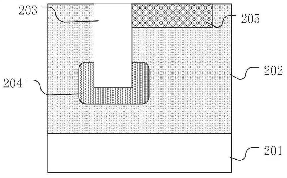
[0004] In the process of forming the body region 205, the floating region 204 with floating potential is affected by factors such as hot carriers and plasma implantation, resulting in unstable and uncontrollable Qg and Crss / Ciss, which brings about the reduction of Qg and Crss / Ciss Adverse effects, and affect device reliability, without affecting the withstand voltage, reduce Qg and Crss / Ciss, continuously improve and enhance the performance of trench MOSFETs, so that trench MOSFET applications can gain a larger market

Method used


Image

  • Groove type MOSFET device and preparation method thereof
  • Groove type MOSFET device and preparation method thereof
  • Groove type MOSFET device and preparation method thereof

Examples


Embodiment Construction

[0034]Various embodiments of the invention will be described in more detail below with reference to the accompanying drawings. In the various drawings, the same elements are denoted by the same or similar reference numerals. For the sake of clarity, various parts in the drawings have not been drawn to scale. Also, some well-known parts may not be shown. For the sake of simplicity, the semiconductor structure obtained after several steps can be described in one figure.

[0035] When describing the structure of a device, when a layer or a region is referred to as being "on" or "over" another layer or another region, it may refer to being directly above another layer or another region, or between it and Other layers or regions are also included between another layer and another region. And, if the device is turned over, the layer, one region, will be "below" or "beneath" the other layer, another region.

[0036] If it is to describe the situation directly on another layer or ...


PUM


Abstract

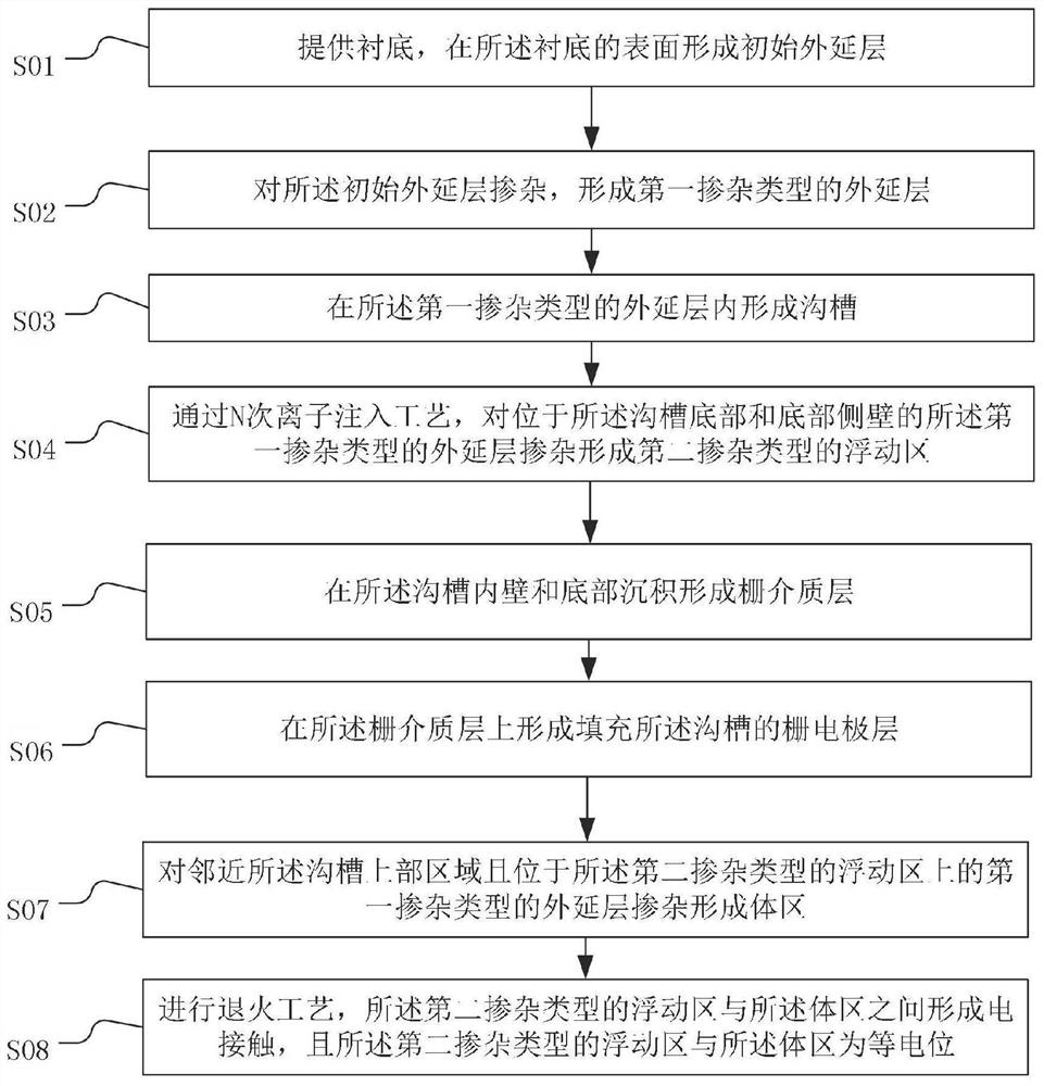
The invention provides a groove type MOSFET (Metal-Oxide-Semiconductor Field Effect Transistor) device. The groove type MOSFET device comprises an epitaxial layer of a first doping type located on a substrate; the groove is positioned in the epitaxial layer of the first doping type; the body region is positioned in an upper region in the epitaxial layer of the first doping type and is adjacent to the groove; the floating region of the second doping type is located in the epitaxial layer of the first doping type and is adjacent to the bottom of the groove and the side wall of the bottom of the groove; the floating region of the second doping type is in electric contact with the body region, and the floating region of the second doping type and the body region are equipotential. Based on the groove type MOSFET device, the withstand voltage BV of the groove type MOSFET device is improved, Crs / Ciss is reduced, and the reliability of the groove type MOSFET device is further improved.

Description

technical field [0001] The present invention relates to the technical field of semiconductor devices, in particular to a trench MOSFET device and a preparation method thereof. Background technique [0002] Power MOSFET (Metal Oxide Semiconductor Field-Effect Transistor) is a multi-subconduction device with a wide variety and rapid change is the current status of power MOSFET applications. Power MOSFETs are mainly trench-type power MOSFETs, and trench-type MOSFETs It is a device with a vertical conductive channel. When the trench MOSFET is in the on state, the current will flow vertically from the drain terminal to the source terminal. Trench MOSFET has the advantages of low on-resistance, small gate leakage current, and high switching rate. These advantages make it widely used in industrial control, aerospace, communications, automobiles, computers and portable appliances, home appliances, office supplies, etc. , especially in the application of switching power supply has a...

Claims


Application Information

Patent Timeline
IPC IPC(8): H01L29/78H01L29/423H01L21/265H01L21/336
CPCH01L29/66666H01L29/7827H01L29/4236H01L21/26513
Inventor 楼颖颖李铁生杨乐
Owner 旭矽半导体(上海)有限公司
Learn More