
Method for manufacturing p-type group III nitride semiconductor

A technology of nitride semiconductor and manufacturing method, which is applied to semiconductor devices, electrical components, circuits, etc., can solve the problems of unobserved detachment and inability to obtain high carrier concentration, and achieve the effect of low resistance and realization of resistance.

Pending Publication Date: 2022-03-01
TOYODA GOSEI CO LTD
View PDF5 Cites 0 Cited by
  • Summary
  • Abstract
  • Description
  • Claims
  • Application Information

AI Technical Summary

Problems solved by technology

In addition, no detachment of H by heat treatment was observed
Therefore, it is shown that by Mg generated from overdoped Mg 2 N 3 , Nitrogen vacancies to compensate the carriers, can not get high carrier concentration

Method used


Image

  • Method for manufacturing p-type group III nitride semiconductor
  • Method for manufacturing p-type group III nitride semiconductor
  • Method for manufacturing p-type group III nitride semiconductor

Examples


Embodiment 1

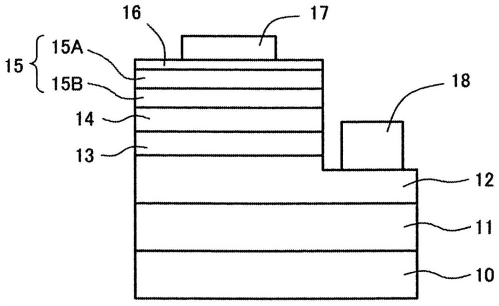
[0046] figure 1 It is a figure showing the structure of the light emitting element of Example 1. It is a flip-chip ultraviolet light-emitting element, which has a substrate 10, a buffer layer 11, an n-contact layer 12, a light-emitting layer 13, an electron blocking layer 14, a p-contact layer 15, a transparent electrode 16, a p-electrode 17, and an n-electrode 18.

[0047] (composition of each layer)

[0048] First, the configuration of each layer of the light-emitting element of Example 1 will be described.

[0049] The substrate 10 is a growth substrate made of sapphire. The thickness of the substrate 10 is, for example, 900 μm. In addition to sapphire, AlN, Si, SiC, ZnO, etc. can also be used.

[0050] The buffer layer 11 is located on the substrate 10 . The buffer layer 11 has a structure in which three layers of a core layer, a low-temperature buffer layer, and a high-temperature buffer layer are laminated in this order. The core layer is composed of undoped AlN g...


PUM

PropertyMeasurementUnit
thicknessaaaaaaaaaa
thicknessaaaaaaaaaa
thicknessaaaaaaaaaa

Abstract

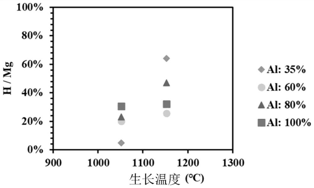
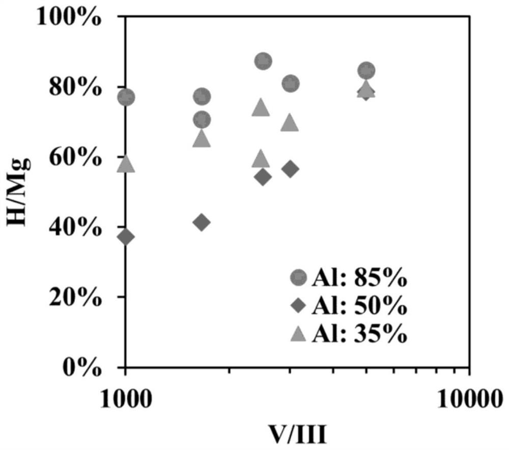
The present invention relates to a method for manufacturing a p-type group III nitride semiconductor containing Al as an essential constituent element. The carrier concentration of a p-type group III nitride semiconductor containing Al as an essential constituent element is improved. An electron blocking layer (14) comprising Mg-doped AlGaN is formed on the light-emitting layer (13) by an MOCVD method. The electron blocking layer (14) is formed such that the ratio H / Mg of the H concentration to the Mg concentration before the heat treatment for p-type formation is 50-100%. The H / Mg may be controlled by the growth temperature, V / III ratio, Mg concentration, etc. of the electron blocking layer (14).

Description

technical field [0001] The present invention relates to a method for producing a p-type Group III nitride semiconductor containing Al as an essential constituent. Background technique [0002] In an ultraviolet light-emitting device made of Group III nitride semiconductors, an electron blocking layer made of p-AlGaN is formed on the light-emitting layer to prevent electrons from diffusing to the p side and improve luminous efficiency. [0003] In Non-Patent Document 1, it is shown that in figure 2 and image 3 H in GaN, AlN + , H - The boundary of the formation energy (the maximum value of the formation energy relative to the Fermi level) is located near the conduction band 2.5eV away from AlN, GaN and H + , H - The boundary position of the formation energy (0.5eV away from the conduction band) is quite different. In addition, it has been shown that when Mg is doped into GaN or AlN, the formation energy of Mg—H is lower than that of Mg alone, so it is easy to be doped ...

Claims


Application Information

Patent Timeline
Patent Type & Authority Applications(China)
IPC IPC(8): H01L33/00H01L33/14
CPCH01L33/007H01L33/14
Inventor 永田贤吾
Owner TOYODA GOSEI CO LTD
Learn More