Light-gathering cavity of lamp pump laser and lamp pump laser
A technology of pumping lasers and concentrating cavities, applied in the field of lasers, can solve problems such as low electro-optical efficiency
- Summary
- Abstract
- Description
- Claims
- Application Information
AI Technical Summary
Problems solved by technology
Method used
Image
Examples
Embodiment 1
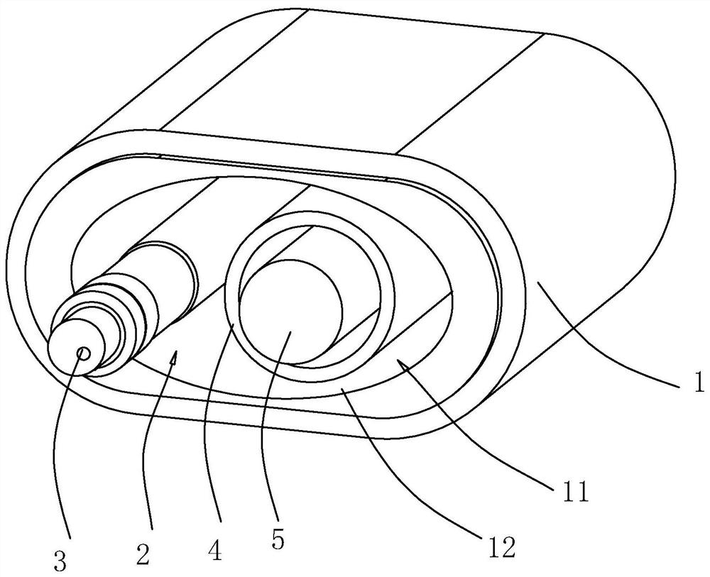
[0035] Embodiment 1 of the present application discloses a light collecting cavity of a lamp pumped laser. refer to figure 1 , a concentrating cavity of a lamp-pumped laser includes a ceramic cavity body 1, a cavity 11 is opened in the ceramic cavity body 1, and the ceramic cavity body 1 is formed by sintering ceramic materials.
[0036] A xenon lamp 3 and a laser crystal 5 are fixed in the cavity 11 of the ceramic cavity body 1 . The xenon lamp 3 and the laser crystal 5 penetrate into the ceramic cavity body 1, so that the ceramic cavity body 1 wraps the outside of the xenon lamp 3 and the laser crystal 5, and the cavity 11 of the ceramic cavity body 1 provides a closed pump light reflection space for the xenon lamp 3 , so that the pump light emitted by the xenon lamp 3 is reflected onto the laser crystal 5, and the energy level transition of the laser crystal 5 occurs to generate laser gain.
[0037] As an optional solution, there is a water layer 2 formed by cooling water...
Embodiment 2
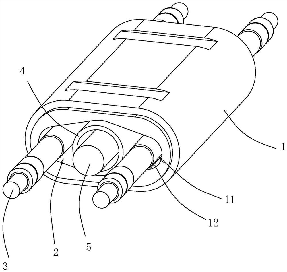
[0055] Embodiment 2 of the present application discloses a light collecting cavity of a lamp pumped laser. refer to figure 2 , the difference from Embodiment 1 is that there are two xenon lamps 3 in the cavity 11 of the ceramic chamber body 1, and the two xenon lamps 3 are symmetrically arranged on both sides of the laser crystal 5, and the two xenon lamps 3 can increase the pumping light. Power: The cavity 11 of the ceramic cavity body 1 is arranged in a rhombus shape, which is convenient for the inner wall of the cavity 11 to reflect the pumping light.
[0056] Embodiment 2 of the present application discloses an implementation principle of a light-collecting cavity of a lamp-pumped laser: the implementation principle is the same as that in Embodiment 1, and will not be repeated here.
Embodiment 3
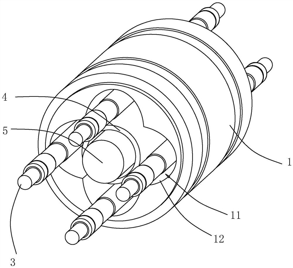
[0058] Embodiment 3 of the present application discloses a light-gathering cavity of a lamp-pumped laser, referring to image 3 , the difference from Embodiment 1 is that there are four xenon lamps 3 in the cavity 11 of the ceramic chamber body 1, and the four xenon lamps 3 are evenly distributed along the circumference of the laser crystal 5, and the four xenon lamps 3 can increase the intensity of the pump light. Power: The cavity 11 of the ceramic cavity body 1 is in the shape of cross petals, which is convenient for the inner wall of the cavity 11 to reflect the pump light, so that the pump light can be irradiated on the laser crystal 5, and the diameter of the laser crystal 5 is generally >15mm.
[0059] Embodiment 3 of the present application discloses an implementation principle of a light-collecting cavity of a lamp-pumped laser: the implementation principle is the same as that in Embodiment 1, and will not be repeated here.
[0060] In combination with Embodiment 1, E...
PUM
| Property | Measurement | Unit |
|---|---|---|
| Tube wall thickness | aaaaa | aaaaa |
Abstract
Description
Claims
Application Information
 - R&D
- Intellectual Property
- Life Sciences
- Materials
- Tech Scout
- Unparalleled Data Quality
- Higher Quality Content
- 60% Fewer Hallucinations
Browse by: Latest US Patents, China's latest patents, Technical Efficacy Thesaurus, Application Domain, Technology Topic, Popular Technical Reports.
© 2025 PatSnap. All rights reserved.Legal|Privacy policy|Modern Slavery Act Transparency Statement|Sitemap|About US| Contact US: help@patsnap.com


