Automatic pump production line

An automated production line and workbench technology, applied in the field of automation, can solve problems such as the lack of a limit structure for water pumps, difficult cleaning of polishing equipment, and affecting processing effects, etc., to achieve the effects of preventing displacement, improving cleaning effects, and saving costs

Pending Publication Date: 2022-03-04
安徽岳泉泵业制造有限公司
View PDF9 Cites 3 Cited by
  • Summary
  • Abstract
  • Description
  • Claims
  • Application Information

AI Technical Summary

Problems solved by technology

[0003] In the existing automatic production line of water pumps, it is generally necessary to polish the casing of the water pump. However, during the polishing process, a large amount of waste chips are splashed everywhere, which not only easily pollutes the environment, but also makes it difficult to clean the inside of the polishing equipment. In the automatic processing process, the conveyor belt is usually used to transport the water pump casing. The water pump lacks an effective limit structure on the surface of the conveyor belt, and it is easy to shift during the processing process, which affects the processing effect.

Method used


Image

  • Automatic pump production line
  • Automatic pump production line
  • Automatic pump production line

Examples


Embodiment 1

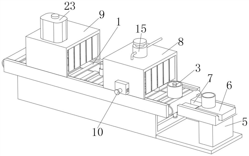
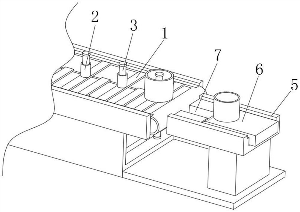
[0025] refer to Figure 1-2 , an automatic pump production line, including a workbench, the upper surface of the workbench is provided with a conveying assembly, the conveying assembly is composed of several conveying plates 1 and a conveying belt, and several conveying plates 1 form a hollowed-out conveying belt, conveying The upper surface of the board 1 is fixedly connected with the sleeve 2, the inner wall of the sleeve 2 is threadedly connected with the feeding column 3, the upper surface of the workbench is fixedly connected with the feeding table 5, and the upper surface of the feeding table 5 is provided with a feeding conveyor belt 6 , and the left side of the loading platform 5 is provided with a feeding port 7, the position of the feeding port 7 corresponds to the sleeve 2, and the feeding port 7 matches the sleeve 2.

[0026] In this embodiment, by setting the conveying plate 1, the sleeve 2 and the feeding column 3, and then cooperating with the feeding port 7 on ...

Embodiment 2

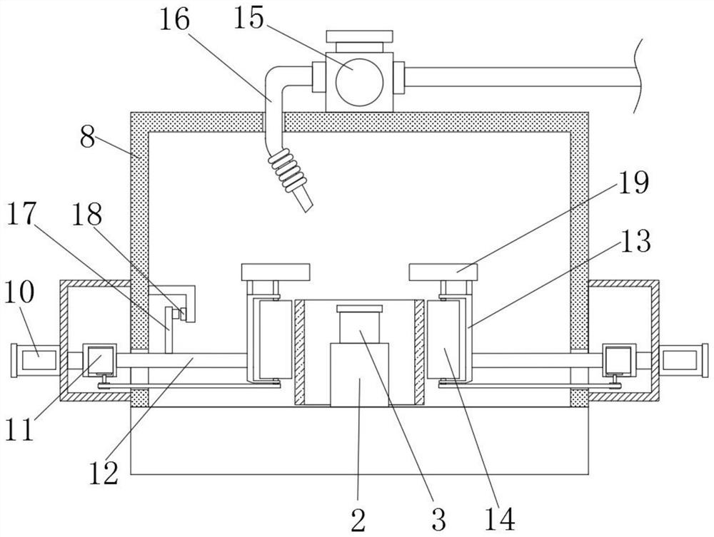
[0028] refer to Figure 3-4 , different from Example 1, the upper surface of the workbench is respectively provided with a polishing box 8 and a cleaning box 9, the conveying assembly passes through the polishing box 8 and the cleaning box 9 successively, and the front and rear surfaces of the polishing box 8 are provided with electric push rods 10. The telescoping end of the electric push rod 10 is fixedly connected with a driving motor 11, and the surface of the driving motor 11 is fixedly connected with an extension rod 12, and the end of the extension rod 12 extends to the inside of the polishing box 8, and is fixedly connected with a U-shaped plate 13 , the inner wall of the U-shaped plate 13 is rotatably connected with a polishing cylinder 14 through a rotating shaft.

[0029] The upper surface of polishing box 8 is provided with delivery pump 15, and the output end of delivery pump 15 is provided with shower nozzle 16, and the bottom end of shower nozzle 16 extends to t...

Embodiment 3

[0034] refer to Figure 5 , different from Embodiment 1, the upper surface of the cleaning box 9 is respectively provided with a cleaning agent box 23, and the upper surface of the cleaning box 9 is embedded with a water pipe, and the inner top wall of the cleaning box 9 is provided with a cleaning pump 24, and the cleaning pump The output end of 24 is provided with spray pipe 4, and the input end of cleaning pump 24 communicates with cleaning agent box 23 and water pipe respectively through three-way pipe.

[0035] In this embodiment, two mutually symmetrical cleaning rollers 22 are arranged in the cleaning box 9, and the compression spring 21 is used to drive the cleaning rollers 22 to be close to the shell surface of the water pump, not only applicable to water pump casings of different sizes, but also The cleaning effect is improved.


PUM


Abstract

The automatic pump production line comprises a workbench, a conveying assembly is arranged on the upper surface of the workbench, the conveying assembly is composed of a plurality of conveying plates and a conveying belt, the conveying plates form a conveying belt with the hollow surface, and sleeves are fixedly connected to the upper surfaces of the conveying plates. According to the automatic pump production line, the conveying plate, the sleeve and the feeding column are arranged and matched with the feeding opening in the surface of the feeding table, the feeding column can be driven to rotate and penetrate through the feeding opening in the moving process of the conveying plate, and meanwhile the feeding column is inserted into a water pump shell from the lower portion; and the water pump shell is fixed to the surface of the conveying belt through the sleeve and the feeding column, subsequent machining treatment on the water pump shell is facilitated, displacement of the water pump shell in the machining process is prevented, the machining stability is improved, and the machining efficiency is improved. And the processing efficiency can be improved.

Description

technical field [0001] The invention relates to the technical field of automation, in particular to an automatic pump production line. Background technique [0002] A water pump is a machine that transports or pressurizes a liquid. It transmits the mechanical energy of the prime mover or other external energy to the liquid to increase the energy of the liquid. It is mainly used to transport liquids including water, oil, acid and alkali, emulsions, and suspoemulsions. And liquid metal, etc., according to the type, there are centrifugal pumps, axial flow pumps and mixed flow pumps. [0003] In the existing automatic production line of water pumps, it is generally necessary to polish the casing of the water pump. However, during the polishing process, a large amount of waste chips are splashed everywhere, which not only easily pollutes the environment, but also makes it difficult to clean the inside of the polishing equipment. In the automatic processing process, the conveyor ...

Claims


Application Information

Patent Timeline
Patent Type & Authority Applications(China)
IPC IPC(8): B24B29/04B24B41/04B24B47/12B24B55/06B24B57/02B24B41/00B24B41/06B08B5/02B08B3/02B08B1/02B08B13/00
CPCB24B29/04B24B41/04B24B47/12B24B55/06B24B57/02B24B41/005B24B41/06B08B5/02B08B3/022B08B1/02B08B13/00
Inventor 夏春林
Owner 安徽岳泉泵业制造有限公司
Why Eureka
Try Eureka