
Laser welding system and method

A laser welding and laser technology, applied in laser welding equipment, welding equipment, metal processing equipment and other directions, can solve the problems of low welding accuracy and quality, high welding defect rate, and inability to press the welding position of the junction box well. To achieve the effect of improving welding production efficiency and welding quality, and improving the pressing effect

Pending Publication Date: 2022-03-08
SHENZHEN HYMSON LASER INTELLIGENT EQUIP CO LTD
View PDF0 Cites 2 Cited by
  • Summary
  • Abstract
  • Description
  • Claims
  • Application Information

AI Technical Summary

Problems solved by technology

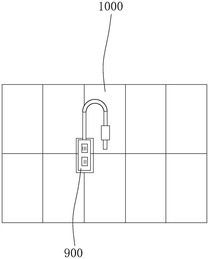
[0004] In the current laser welding process, the welding indenter assembly is usually used to compress the welding material, but the moving position of the commonly used welding indenter assembly is set in advance during the welding process, and cannot be self-adjusted according to the actual situation. , when the placement position of the junction box on the photovoltaic module is slightly deviated, the welding head assembly cannot well press the welding position on the junction box, resulting in poor pressing effect; moreover, the welding of each junction box The point thickness is different, and the existing soldering head assembly cannot compress the soldering point of the junction box
Therefore, the laser welding system applied to the junction box has the problems of low welding accuracy and quality, and high welding defective rate

Method used


Image

  • Laser welding system and method
  • Laser welding system and method
  • Laser welding system and method

Examples


Embodiment Construction

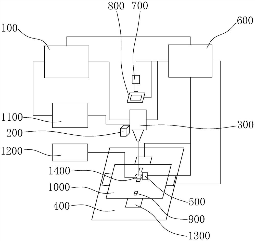
[0041] The idea, specific structure and technical effects of the present invention will be clearly and completely described below in conjunction with the embodiments and accompanying drawings, so as to fully understand the purpose, features and effects of the present invention. Apparently, the described embodiments are only some of the embodiments of the present invention, rather than all of them. Based on the embodiments of the present invention, other embodiments obtained by those skilled in the art without creative efforts belong to The protection scope of the present invention. In addition, all the connection / connection relationships mentioned in this article do not refer to the direct connection of components, but mean that a better connection structure can be formed by adding or reducing connection accessories according to specific implementation conditions. The various technical features in the invention can be combined interactively on the premise of not conflicting wi...


PUM


Abstract

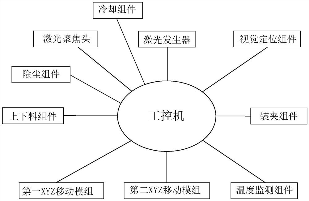
According to the laser welding system and method, in the laser welding system, a feeding and discharging assembly can transfer a photovoltaic assembly with a junction box to a workbench; the clamping assembly is arranged on the workbench so as to clamp and position the photovoltaic assembly. The welding pressure head assembly comprises a connecting plate, a mounting base, an elastic piece, a pressure head and a position detector, the connecting plate is connected with the first mechanical arm and the mounting base, the upper end of the elastic piece is connected with the mounting base, the lower end of the elastic piece is connected with the pressure head, the position detector is arranged on the mounting base, and the pressure head is provided with an induction piece located below the position detector; the laser generator is connected with the laser focusing assembly so that laser can be transmitted to the laser focusing assembly. The laser focusing assembly is connected with the second mechanical arm; the visual positioning assembly is located above the workbench, the visual positioning assembly and the position detector are electrically connected with the industrial personal computer, and the industrial personal computer is electrically connected with the laser generator, the first mechanical arm and the second mechanical arm. The welding reject ratio can be reduced, and the welding precision and quality of the junction box are improved.

Description

technical field [0001] The invention relates to the technical field of laser welding, in particular to a laser welding system and method. Background technique [0002] Photovoltaic cell modules, as a technology that utilizes solar energy to generate electricity, have the advantages of being green and environmentally friendly, and have been popularized in many fields; because of their high photoelectric conversion efficiency, they have become mainstream products in the photovoltaic solar power generation market. Among them, photovoltaic cell components mainly include cells, interconnection bars, bus bars, tempered glass, EVA (ethylene-vinyl acetate copolymer), backplane, aluminum alloy, silica gel and junction boxes and other components. [0003] The junction box of the photovoltaic module and the bus bar on the photovoltaic cell realize the connection of the electricity generated by the solar cell with the external line through welding process. Welding the junction box is t...

Claims


Application Information

Patent Timeline
Patent Type & Authority Applications(China)
IPC IPC(8): B23K26/21B23K26/70
CPCB23K26/21B23K26/702
Inventor 周宇超赵盛宇林国栋何颖波毛俊波郭洪涛张日明谭淼
Owner SHENZHEN HYMSON LASER INTELLIGENT EQUIP CO LTD
Learn More