
Packaging method of fan-out wafer level packaging structure

A technology of wafer-level packaging and packaging methods, which is applied in the manufacturing of electrical components, electric solid-state devices, semiconductor/solid-state devices, etc., can solve the problems of poor semiconductor chip contact, affecting the yield of wafer packaging, and wafer warpage. , to achieve the effect of simple and feasible method, improving electrical connection performance and eliminating warping

Pending Publication Date: 2022-03-08
SJ SEMICON JIANGYIN CORP
View PDF0 Cites 0 Cited by
  • Summary
  • Abstract
  • Description
  • Claims
  • Application Information

AI Technical Summary

Problems solved by technology

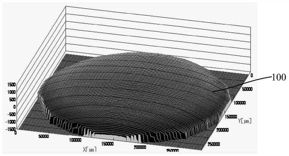
[0005] In view of the above-mentioned shortcomings of the prior art, the purpose of the present invention is to provide a packaging method of fan-out wafer level packaging structure, which is used to solve the problem of the fan-out wafer level packaging in the prior art after the semiconductor chip is plastic-encapsulated. Warping of the wafer will cause the risk of poor contact between the subsequent rewiring layer and the semiconductor chip, which will affect the yield of the wafer package, etc.

Method used


Image

  • Packaging method of fan-out wafer level packaging structure
  • Packaging method of fan-out wafer level packaging structure
  • Packaging method of fan-out wafer level packaging structure

Examples


Embodiment Construction

[0044] Embodiments of the present invention are described below through specific examples, and those skilled in the art can easily understand other advantages and effects of the present invention from the content disclosed in this specification. The present invention can also be implemented or applied through other different specific implementation modes, and various modifications or changes can be made to the details in this specification based on different viewpoints and applications without departing from the spirit of the present invention.

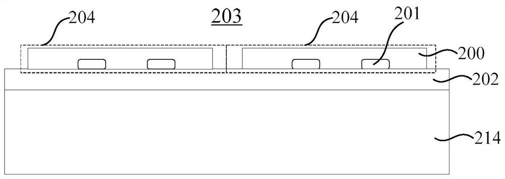
[0045] see Figure 2 to Figure 16 . It should be noted that the diagrams provided in this embodiment are only schematically illustrating the basic idea of ​​the present invention, so that only the components related to the present invention are shown in the diagrams rather than the number, shape and Dimensional drawing, the type, quantity and proportion of each component can be changed arbitrarily during actual implementation, and th...


PUM


Abstract

The invention provides a packaging method of a fan-out type wafer level packaging structure, which comprises the following steps of: providing more than two semiconductor chips and bonding the semiconductor chips on a bonding layer; packaging the semiconductor chip by using a plastic packaging layer; removing the bonding layer, and forming a rewiring layer on the semiconductor chips to realize interconnection of the semiconductor chips; the rewiring layer comprises at least one sub-rewiring layer which is stacked in sequence. The method for forming the sub-rewiring layer comprises the following steps: forming a dielectric layer on a semiconductor chip; forming a through hole in the dielectric layer by adopting a photoetching process; baking the dielectric layer with the through hole to eliminate warping of the dielectric layer around the through hole; curing the dielectric layer; and forming a patterned metal wiring layer corresponding to the through hole in the through hole and on the dielectric layer, and forming a metal bump on the patterned metal wiring layer. According to the method, the morphology of the dielectric layer around the through hole can be effectively improved, the upwarp of the dielectric layer around the through hole is eliminated, and the electrical connection performance of the rewiring layer formed subsequently and the semiconductor chip is improved.

Description

technical field [0001] The invention belongs to the technical field of semiconductor packaging, in particular to a packaging method of a fan-out wafer level packaging structure. Background technique [0002] With the rapid development of the integrated circuit manufacturing industry, people's requirements for the packaging technology of integrated circuits are also increasing. The existing packaging technologies include ball grid array packaging (BGA), chip size packaging (CSP), wafer level packaging (WLP) ), three-dimensional packaging (3D) and system in package (SiP), etc. Among them, wafer-level packaging (WLP) is gradually adopted by most semiconductor manufacturers due to its outstanding advantages. All or most of its process steps are completed on silicon wafers that have completed the previous process, and finally the wafer Direct dicing into separate individual devices. Wafer-level packaging (WLP) has its unique advantages: ① high packaging processing efficiency, m...

Claims


Application Information

Patent Timeline
Patent Type & Authority Applications(China)
IPC IPC(8): H01L21/50H01L21/56H01L21/60
CPCH01L21/50H01L21/561H01L21/568H01L24/03H01L24/11H01L2224/0231H01L2224/02379H01L2224/03H01L2224/11G07C9/00309G07C9/00563G07C9/00571G07C9/00944H04L9/0819H04L9/0861H04L9/0894H01L23/3128H01L23/5389H01L24/19H01L24/96H01L2224/12105H01L2924/3511H01L24/20H01L25/50H01L25/0655H01L21/6836H01L24/73H01L2224/73209H01L2924/01028H01L2924/01029H01L2924/01079H01L2924/014H01L2924/07025H01L2924/186H01L2924/37001
Inventor 赵海霖
Owner SJ SEMICON JIANGYIN CORP
Learn More