Manufacturing method of capacitive coupling type slip ring

A production method and capacitive coupling technology, applied in the manufacture of slip rings, etc., can solve the problems of high cost and increased equipment volume, and achieve the effects of improving utilization, increasing equipment volume, and increasing costs

Pending Publication Date: 2022-03-08
BEIJING HANGXING MACHINERY MFG CO LTD
View PDF0 Cites 2 Cited by
  • Summary
  • Abstract
  • Description
  • Claims
  • Application Information

AI Technical Summary

Problems solved by technology

[0008] In view of the above analysis, the present invention aims to provide a manufacturing method of a capacitively coupled slip ring to solve the problem that the existing slip ring increases the communication rate of the entire system by widening the width of the rotating disk, which leads to an increase in the size of the device, and high cost problem

Method used


Image

  • Manufacturing method of capacitive coupling type slip ring
  • Manufacturing method of capacitive coupling type slip ring
  • Manufacturing method of capacitive coupling type slip ring

Examples


Embodiment 1

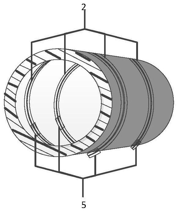
[0043] A specific embodiment of the present invention discloses a capacitively coupled slip ring, which includes a rotating disc 1, a sending unit and a receiving unit.

[0044] Such as figure 1 As shown, the sending unit includes a sending antenna 2 and a data processing unit at the sending end, the data processing unit at the sending end includes a sending circuit board and a data line, and both the sending antenna 2 and the data line are connected to the sending circuit board. Exemplarily, the sending antenna 2 is connected to the sending circuit board in the form of a connector. The sending circuit board is fixed on the rotating disk.

[0045] The shape of the transmitting antenna adopted in the present invention is flat, or strip-shaped.

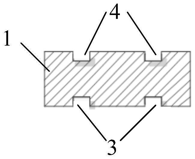
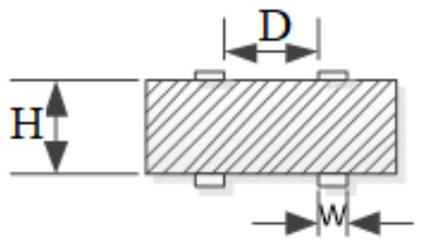
[0046] The rotating disk is hollow inside and has a large aperture ring shape, and its outer surface is provided with a first groove 3 arranged circumferentially. The shape of the first groove 3 matches the shape of the transmitting a...

Embodiment 2

[0059] Another specific embodiment of the present invention discloses a CT detection device. The capacitively coupled slip ring is one of the key components of the CT, and is used for power and data transmission between the CT rotor end and the stator end.

[0060] With the advancement of CT technology, the amount of data collected by detectors is increasing day by day. The required data transmission bandwidth can be estimated by Equation 6, and the following relationship between the number of CT layers and data bandwidth can be obtained. Formula 6:

[0061]

[0062] Among them, S is the data transmission bandwidth; P is the number of multi-layer spiral CT DAS channels; n is the number of single-layer spiral CT detectors; m is the number of single-sampling data bits for each detector; v is the rotation speed of the slip ring; f is the sampling frequency.

[0063] The corresponding relationship between the number of CT layers and the data bandwidth is as follows: Figure 9...

Embodiment 3

[0068] Existing transmitting antennas are usually capacitively coupled antennas, which are usually made of printed circuit boards (PCB). The PCB board is based on an insulating board, cut to a certain size, with at least one conductive pattern on it, and holes (such as component holes, fastening holes, metallized holes, etc.), used to replace the electronic components of the previous installation Chassis, and realize the interconnection between electronic components. Because they are made using electronic printing, they are called "printed" circuit boards. The current PCB board is mainly composed of lines and graphics, dielectric layers, holes, solder resist ink, silk screen and surface treatment.

[0069] The advantages of capacitive coupling antennas made of PCB boards are: due to the repeatability (reproducibility) and consistency of PCB board graphics, wiring and assembly errors are greatly reduced, and antenna maintenance, debugging and inspection time are saved. Standa...


PUM


Abstract

The invention relates to a manufacturing method of a capacitive coupling type slip ring, belongs to the technical field of X-ray computed tomography (CT) imaging technology, and solves the problems that the equipment size is increased and the cost is high due to the fact that the communication rate of the whole system is increased by widening the width of a rotating disc of an existing slip ring. The manufacturing method of the capacitive coupling type slip ring comprises the following steps: step 1, selecting a disc body; 2, a first groove is formed in the periphery of the inner surface of the tray body; step 3, fixing the transmitting end data processing unit on the disk body; the transmitting antenna is fixed in the first groove. According to the invention, multi-channel data transmission is realized.

Description

technical field [0001] The present invention relates to the technical field of X-ray computed tomography imaging technology ("CT technology" for short), in particular to a manufacturing method of a capacitively coupled slip ring. Background technique [0002] X-ray computed tomography imaging technology (abbreviated as "CT technology") is highly valued and widely used in the field of security inspection due to its own unique advantages. [0003] The capacitively coupled slip ring is one of the key components of the CT, which is used for power and data transmission between the rotor end and the stator end of the CT. [0004] At present, the commonly used non-contact conductive slip rings and data transmission methods between rotating bodies mainly include wireless capacitive coupling transmission and optical transmission. [0005] The capacitive coupling slip ring realizes signal transmission through the capacitive coupling between the flexible antenna around the outer edge ...

Claims


Application Information

Patent Timeline
Patent Type & Authority Applications(China)
IPC IPC(8): H01R43/10
CPCH01R43/10
Inventor 刘晓超徐圆飞李保磊翟利梁丽华
Owner BEIJING HANGXING MACHINERY MFG CO LTD
Why Eureka
Try Eureka