
Hybrid power generation system

A hybrid power generation and generator technology, which is applied in electrical signal transmission systems, wind power generation, photovoltaic power generation, etc., can solve the problems of reduced rotation speed, increased power generation, and increased rotational force, so as to achieve increased rotational torque and power generation. Effects of improved energy efficiency and increased rotation speed

Pending Publication Date: 2022-03-11
李允源
View PDF14 Cites 0 Cited by
  • Summary
  • Abstract
  • Description
  • Claims
  • Application Information

AI Technical Summary

Problems solved by technology

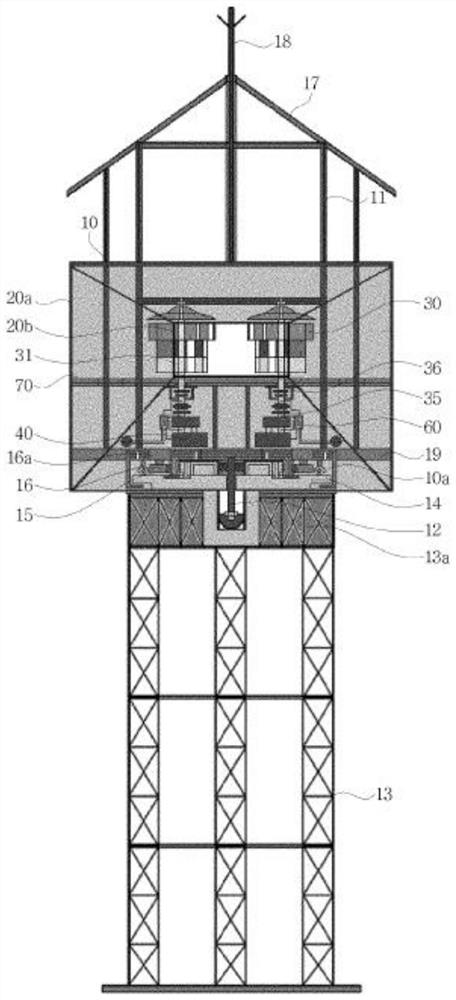
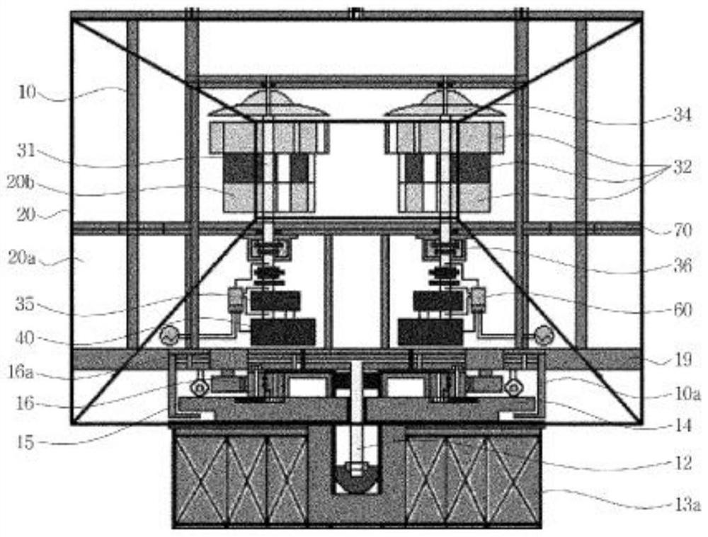
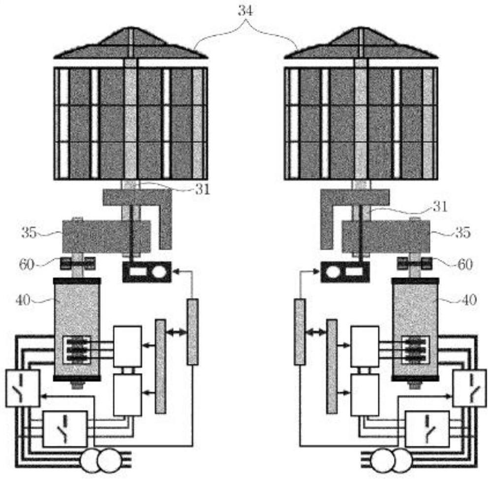
[0012] The object of the present invention is to provide a hybrid power generation system comprising blades arranged on a vertical shaft, which rotate with less noise and vibration, and which includes a wind collecting duct to increase the wind speed for rapidly rotating the blades to improve the efficiency of wind energy. The blades are equipped with compartments that can capture wind, so that the wind energy utilization efficiency is high and the rotational force can be increased, which solves the problem that the blades encounter headwind and tailwind at the same time, which reduces the rotational speed of the blades and hinders the power generation. When meeting against the wind, only the downwind is introduced into the blade compartment, and the solar module concentrating device is installed on the upper part of the system, so that the electric energy generated by it can drive the motor installed in the air collecting pipe even when there is no wind. Make the wind guiding device rotate, so as to artificially create high-speed wind and increase the power generation

Method used


Image

  • Hybrid power generation system
  • Hybrid power generation system
  • Hybrid power generation system

Examples


Embodiment Construction

[0052] The specific viewpoints and specific technical features of the present invention will become more clear based on the following specific contents and embodiments related to the accompanying drawings. It should be noted that, when assigning reference numerals to components in the drawings in this specification, the same components are given the same reference numerals as much as possible even though they are shown in different drawings. In addition, when explaining one embodiment of the present invention, the detailed description is omitted when it is judged that a specific description of a related well-known configuration or function may obscure the gist of the present invention.

[0053] In addition, terms such as first, second, A, B, (a), and (b) may be used when describing components of the present invention. These terms are used only to distinguish the constituent elements from other constituent elements, and do not limit the nature, order, sequence, etc. of the corr...


PUM


Abstract

The hybrid power generation system according to an embodiment of the present invention has the effects of including a blade provided on a vertical shaft, having little noise and vibration during rotation, and including a wind collecting pipe to increase the wind speed for rapidly rotating the blade to improve the efficiency of wind energy, and being provided with a compartment capable of collecting wind at the blade, the wind power utilization efficiency is high and the rotational force can be increased, and the wind guide rotating motor provided in the wind collection duct can be driven by solar energy without blowing wind, so that the wind guide rotating blades provided on the same shaft rotate, the wind is accelerated and strongly discharged into the wind collection blades of the turbine module, and the wind power generation efficiency is improved. In this way, the generating capacity can be increased, the danger of the power generation device can be sensed in advance through the Internet of Things technology such as a camera, a fire sensing sensor and an unmanned aerial vehicle and the artificial intelligence (AI) basic technology, the fault danger of the power generation device is greatly reduced, and the system is effectively applied and managed.

Description

technical field [0001] The present invention relates to a power generation device, and in more detail to a hybrid power generation system for obtaining electric energy through wind energy and solar power generation. Background technique [0002] For example, to start a generator to generate electricity, electricity is generated using energy obtained by burning fossil fuels such as coal or petroleum, or utilizing nuclear energy, sunlight, solar heat, wind power, and water power. [0003] Among them, generators using fossil fuels are highly efficient and widely used, but have many problems such as depleting resources and causing environmental pollution, so the use of generators using nuclear energy or the like is gradually expanding. [0004] However, nuclear power has the problem of suffering heavy losses in the event of an accident such as a leak, and residents strongly oppose the location where it is installed, so it is difficult to select a location for installing a genera...

Claims


Application Information

Patent Timeline
Patent Type & Authority Applications(China)
IPC IPC(8): F03D9/00
CPCF03D9/007Y02E10/76H02S50/00Y02E10/56F03D3/0427F05B2240/211F05B2270/32F05B2240/13F05B2220/708H02S10/12H02J7/35H02J7/0048H02J7/0014H02S10/20G08B17/06G08B21/185G08C17/02G08C19/02F03D9/11F03D3/005F03D17/00Y02E10/50Y02E10/74
Inventor 李允源
Owner 李允源
Learn More