Cylindrical grinding machine grinding wheel spindle bearing oil groove milling head device

A technology for spindle bearings and cylindrical grinding machines, which is applied to positioning devices, supports, and milling machine equipment. It can solve problems such as poor surface roughness, oily scales on the surface of workpieces, and reduced processing accuracy. Milling resistance, the effect of improving the rigidity of the oil film

Pending Publication Date: 2022-03-18
BEIJING NO 2 MACHINE TOOL WORKS
View PDF9 Cites 0 Cited by
  • Summary
  • Abstract
  • Description
  • Claims
  • Application Information

AI Technical Summary

Problems solved by technology

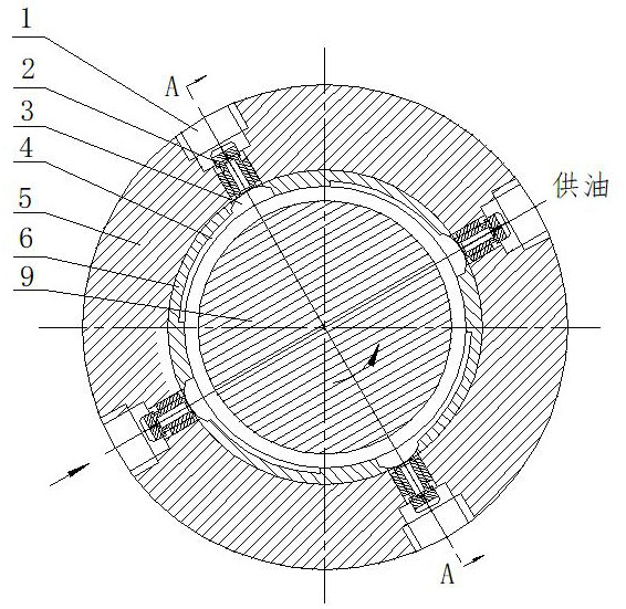
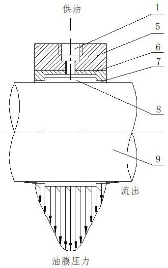
Since the bearing is a bimetallic material, when processing the lead bronze layer, the feed rate is 0.2mm each time. When it is close to the steel substrate, the feed rate is changed by 0.05mm each time. This processing method is prone to the following problems: when the speed is too high It will cause broaching to crawl; when the speed is too high, it will cause broaching vibration; when the turning tool is blunted and the rake angle is improper, it will cause oil scales on the surface of the workpiece. , resulting in the size of the oil groove, the processing quality of the surface roughness is not high
In addition, due to the need to process four oil grooves uniformly distributed on the circumference, the previous process needs to draw a line on the inner hole of the bearing (saving the time of using the dividing head, but reducing the processing accuracy), in each oil groove, the turning tool is repeatedly advanced To, also cause low processing efficiency

Method used


Image

  • Cylindrical grinding machine grinding wheel spindle bearing oil groove milling head device
  • Cylindrical grinding machine grinding wheel spindle bearing oil groove milling head device
  • Cylindrical grinding machine grinding wheel spindle bearing oil groove milling head device

Examples


Embodiment Construction

[0041] see Figure 5 , on the basis of the existing vertical milling machine, this device adds a horizontally extending bracket and a transmission mechanism. One end of the bracket is the installation end, which is fixedly installed on the milling head, and the other end is the working end (end) with the milling cutter. , the original milling cutter located under the main shaft (for the sake of distinction, the original milling cutter installed on the main shaft of the milling machine is called the main shaft milling cutter, and the milling cutter installed at the end of the bracket is called the end milling cutter). At a certain distance, the added bracket is installed on the flange end cover 21 at the lower end of the vertical milling head of the vertical milling machine, and the mounting end of the bracket (the end connected with the milling head) is installed on the flange end cover through the connecting plate 22. The fixed connection on the top, the belt adjustment bolt ...


PUM


Abstract

The invention relates to a cylindrical grinding machine grinding wheel spindle bearing oil groove milling head device which comprises a vertical milling machine and a support extending transversely, the vertical milling machine is provided with a vertical milling head, the milling head is provided with a milling cutter driving shaft, the mounting end of the support is fixedly mounted below the milling head, and the tail end of the support is provided with a tail end milling cutter extending downwards. The tail end milling cutter is in transmission connection with the milling cutter driving shaft through a tail end transmission mechanism, the tail end transmission mechanism is a belt transmission mechanism, a driving wheel of the tail end transmission mechanism is installed on the milling cutter driving shaft, and a driven wheel of the tail end transmission mechanism is installed on a cutter handle of the tail end milling cutter. A cutter handle of the tail end milling cutter is rotationally installed at the tail end of the support through a bearing, the support is made of long and thin U-shaped steel, and the tail end transmission mechanism is arranged in a groove of the U-shaped steel. The method is suitable for machining structures such as a main shaft bearing oil groove, milling resistance can be greatly reduced, vibration, deformation and heating of a cutter and a machined part in the milling process are relieved, and machining quality is improved.

Description

technical field [0001] The invention relates to an oil groove milling head device for a grinding wheel spindle bearing of an outer cylindrical grinder, belonging to the technical field of machinery. Background technique [0002] With the modernization and development of my country's machinery industry, the requirements for high efficiency of parts processing and compressed processing time are increasing day by day. Correspondingly, the processing efficiency of cylindrical grinders is also improving, and the grinding feed rate of the outer circle and end face of parts is increased. Large, and the increase of the load of the large-size grinding wheel has caused an increase in the "holding shaft" failure of the grinding wheel spindle, which shows the limitations of existing milling machines in processing related workpieces. [0003] For example, the existing grinding wheel spindle dynamic and static pressure bearing is made of powder metallurgy sintering of steel sleeve (steel b...

Claims


Application Information

Patent Timeline
Patent Type & Authority Applications(China)
IPC IPC(8): B23C3/28B23Q3/06
CPCB23C3/28B23Q3/06
Inventor 蔡斌赵成利李国想隗婕李硕
Owner BEIJING NO 2 MACHINE TOOL WORKS
Why Eureka
Try Eureka