Handheld electric cutting tool

A cutting tool and hand-held technology, which is applied in the field of hand-held electric cutting tools, can solve the problems of inability to cut hard pipes, limited elasticity of elastic parts, inconvenient use, etc., and achieve good cutting effect, strong adaptability, and convenient adjustment.

Pending Publication Date: 2022-03-22
TAIZHOU JULI TOOLS
View PDF16 Cites 0 Cited by
  • Summary
  • Abstract
  • Description
  • Claims
  • Application Information

AI Technical Summary

Problems solved by technology

[0006] The purpose of the present invention is to provide a hand-held electric cutting tool. During the cutting process, the driving device is used to drive the knife feeding device to work, so as to realize the knife feeding and generate cutting force to cut the pipe, so as to solve the problems in the prior art. The elastic force of the elastic part is limited, resulting in a small cutting force, and it cannot cut high hardness and thick pipes, which is inconvenient to use.

Method used


Image

  • Handheld electric cutting tool
  • Handheld electric cutting tool
  • Handheld electric cutting tool

Examples


Deformed example 1

[0122] The threaded part 1 514 can be formed on the sleeve, and then the sleeve is welded to the feed shaft 504 to achieve the purpose of setting the threaded part 1 514 outside the feed shaft 504 .

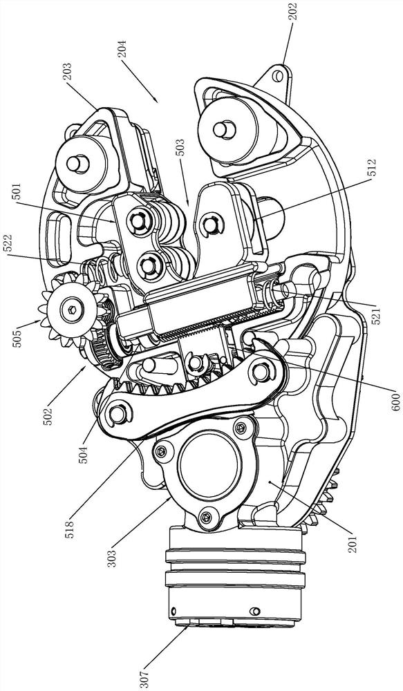
[0123] Such as Figure 5 As shown, in order to cooperate with the reset device 600, a clamping part 1 513 is formed on the end face of the insertion part 1 507;

[0124] The outer wall of the feed shaft 504 forms a threaded part one 514;

[0125] The ends of the reset device 600 are respectively formed with the second clamping part 604 and the second threaded part 606;

[0126] The first clamping part 513 cooperates with the second clamping part 604 , and the first threaded part 514 cooperates with the second threaded part 606 , thereby restricting the free movement of the roller seat 506 and the knife seat 509 .

[0127] The clamping part 1 513 and the clamping part 2 604 can both be tooth-shaped, which can be engaged and clamped; or can be clamped by the cooperation of protru...

Deformed example 2

[0165] The above-mentioned limiting block 603 can also be integrally formed with the cutting seat 203, and it can also be reset by continuing to reverse it when resetting.

[0166] The adjustment mechanism 602 includes a push piece 607, a reset piece 608 and an elastic piece 2 609;

[0167] The pusher 607 is passed through the cutting seat 203, and the part inside the cutting seat 203 is an eccentric shaft. The side wall of the eccentric shaft is against the rear end of the limit block 603. A swing rod 616 is formed along the side wall of the cutting seat 203, and the end of the swing rod 616 protrudes to form a rotating protrusion 615;

[0168] The quantity of the second elastic member 609 is two, all of which are arranged in the cutting seat 203, and the end of the second elastic member 609 is fixed on the pin shaft, and the other end is respectively connected to the side of the rear end of the limit block 603, and the eccentric shaft is located at the two sides. Between tw...

Deformed example 3

[0177] The part of the pusher 607 located inside the cutting seat 203 can also be designed as a camshaft, so as to push the pendulum 616 so that the limit block 603 is pushed.


PUM


Abstract

The invention relates to the technical field of electric tools, in particular to a handheld electric cutting tool which is used for cutting a pipe and comprises a shell, a handle and a handle. The cutter feeding device is rotatably mounted in the shell; a clamping position is arranged in the cutter feeding device, and a cutting knife is arranged on the peripheral side of the clamping position; when the feeding device rotates, the cutting knife executes a cutting action; and the driving device is used for providing power for the execution device. The driving device is used for driving the cutter feeding device to work, cutter feeding is achieved, cutting force is generated, pipes are cut, and the problems that in the prior art, due to the fact that the elastic force of an elastic piece is limited, the cutting force is small, high-hardness and thick pipes cannot be cut, and use is inconvenient are solved.

Description

technical field [0001] The invention relates to the technical field of electric tools, in particular to a hand-held electric cutting tool. Background technique [0002] Thin-walled metal pipe refers to a metal pipe whose wall thickness to outer diameter ratio is not more than 10%. Common materials include copper, stainless steel, carbon steel and aluminum alloy. Thin-walled metal pipes are mainly used in water supply and drainage, gas supply, heating, fire protection and chemical pipeline systems in urban construction. Common cutting equipment for thin-walled metal pipes include hand saws, manual cutters, grinding wheel cutters, angle grinders and other equipment. [0003] But above-mentioned equipment can produce problems such as impurity and burr when using, can seriously affect the normal use of pipe, so hand-held copper pipe cutting tool has appeared on the market. [0004] For example, Chinese patent 2019214354103, which is called a portable automatic pipe cutter, dis...

Claims


Application Information

Patent Timeline
IPC IPC(8): A01G3/08
CPCA01G3/081Y02P70/10
Inventor 张银根何挺伟宁建忠曾鹏
Owner TAIZHOU JULI TOOLS
Why Eureka
Try Eureka