Method for changing Sn-based brazing filler metal welding spot remelting crystal orientation by changing welding parameters

A technology of welding parameters and crystal orientation, applied in the direction of welding/cutting medium/material, welding medium, welding equipment, etc., can solve the problems of poor overall performance of solder joints, achieve enhanced anti-electromigration performance, and inhibit electromigration damage behavior , The effect of improving the mechanical properties

Pending Publication Date: 2022-03-22
BEIJING UNIV OF TECH
View PDF6 Cites 0 Cited by
  • Summary
  • Abstract
  • Description
  • Claims
  • Application Information

AI Technical Summary

Problems solved by technology

[0005] In view of the above problems of Sn-based solder alloys, the overall performance of solder joints is not good, it is necessary to provide a method for changing the remelted crystal orientation of Sn-based solder solder joints by changing welding parameters

Method used


Image

  • Method for changing Sn-based brazing filler metal welding spot remelting crystal orientation by changing welding parameters
  • Method for changing Sn-based brazing filler metal welding spot remelting crystal orientation by changing welding parameters
  • Method for changing Sn-based brazing filler metal welding spot remelting crystal orientation by changing welding parameters

Examples


Embodiment 1

[0041] Embodiment 1: adopt Ag=3.5wt%, Bi=0.5wt%, In=8.0wt%, Sn=88.0wt% solder paste, take it out from the refrigerator as required, and let it stand in the air for 1 hour ; Grind and polish the surface of the pad and fix the pad spacing to 400 μm; fill the solder between the two pads, and use the brazing process as follows: 5°C / s to 150°C → 1°C / s to 190°C → 12°C / s heating to 245°C → heat preservation → cooling to room temperature in air; heat preservation time is 40s.

Embodiment 2

[0042] Embodiment 2: adopt Ag=3.5wt%, Bi=0.5wt%, In=8.0wt%, Sn=88.0wt% solder paste, take it out from the refrigerator as required, and let it stand in the air for 1 hour ; Grind and polish the surface of the pad and fix the pad spacing to 400 μm; fill the solder between the two pads, and use the brazing process as follows: 5°C / s to 150°C → 1°C / s to 190°C → 12°C / s heating to 280°C → heat preservation → cooling to room temperature in air; heat preservation time is 40s.

Embodiment 3

[0043] Embodiment 3: adopt Ag=3.5wt%, Bi=0.5wt%, In=8.0wt%, Sn=88.0wt% paste solder, take it out from the refrigerator according to requirements, and let it stand in the air for 1 hour ; Grind and polish the surface of the pad and fix the pad spacing to 400 μm; fill the solder between the two pads, and use the brazing process as follows: 5°C / s to 150°C → 1°C / s to 190°C → 12°C / s heating to 310°C → heat preservation → cooling to room temperature in air; heat preservation time is 40s.

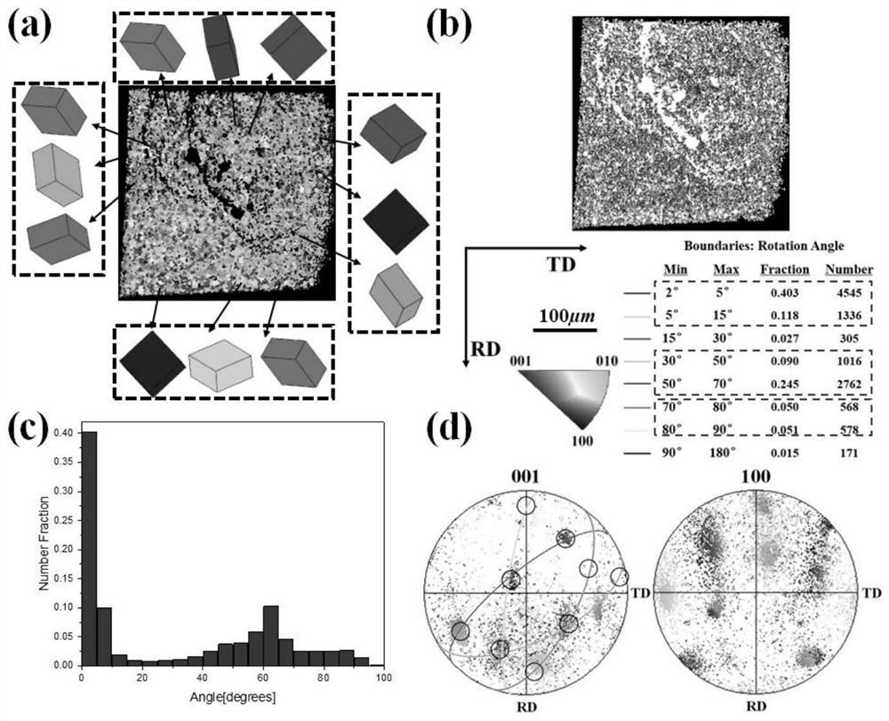
[0044] figure 1 It is the cross-sectional EBSD test diagram of the remelted solder joint in Example 1 at 245°C, wherein (a) grain orientation diagram, (b) grain boundary distribution diagram, (c) misorientation histogram, (d) pole figure, grain The scale bar of the direction diagram and grain boundary distribution diagram is 100 μm. figure 1 It shows that the cross-section of the solder joint is composed of inter-doped and crossed main crystal orientations and fine grain orientations dispersedly...


PUM

PropertyMeasurementUnit
hardnessaaaaaaaaaa
hardnessaaaaaaaaaa

Abstract

The invention discloses a method for changing Sn-based brazing filler metal welding spot remelting crystal orientation by changing welding parameters, and relates to the technical field of material preparation and connection, SABI brazing filler metal serves as a raw material, the remelting temperature ranges from 245 DEG C to 310 DEG C, the method can be applied to low-temperature brazing of electronic packaging components with base materials mainly being Cu/Ni UBM, and by setting the technological parameters, the Sn-based brazing filler metal welding spot remelting crystal orientation can be changed. The crystal orientation of the obtained welding spot is different from that of common brazing filler metal such as SAC305, crystal orientations in the welding spot are mutually crossed and doped, the crystal orientations are broken and disordered, crossed crystals and multi-double twin crystals are formed, and due to the existence of the crossed crystals and the multi-double twin crystals, the anisotropy degree of the Sn-based welding spot is greatly reduced, and the performance is uniform.

Description

technical field [0001] The invention relates to the technical field of material preparation and connection, in particular to a method for changing the remelted crystal orientation of Sn-based solder joints by changing welding parameters. Background technique [0002] With the miniaturization, high density and multi-purpose of microelectronic devices and microsystem packages, the thermal-mechanical and electrical loads carried by micro-interconnection solder joints are becoming heavier and heavier, so the requirements for the reliability of interconnection solder joints Also getting higher and higher. Usually, lead-free solder interconnection solder joints are only composed of one or a few grains, showing obvious anisotropy, and interconnection solder joints often undergo recrystallization behavior during service. Different from conventional recrystallization, the recrystallization process in solder joints is accompanied by the aggregation and growth of intermetallic compoun...

Claims


Application Information

Patent Timeline
Patent Type & Authority Applications(China)
IPC IPC(8): B23K1/008B23K1/012B23K35/02B23K35/28
CPCB23K1/012B23K1/008B23K35/025B23K35/282
Inventor 汉晶曹恒郭福马立民晋学轮孟洲吕伊铭贾强周炜籍晓亮
Owner BEIJING UNIV OF TECH
Why Eureka
Try Eureka