Method for separating roundness error of core shaft in rotation error of main shaft of numerical control machine tool

A technology of rotation error and roundness error, which is applied in the field of separation of mandrel roundness error in the spindle rotation error of CNC machine tools, can solve problems such as difficult and cumbersome clamping, errors, and difficulty in realization, and achieve low equipment performance requirements and good separation accuracy , the effect of simple operation

Pending Publication Date: 2022-03-22
HUAZHONG UNIV OF SCI & TECH
View PDF0 Cites 0 Cited by
  • Summary
  • Abstract
  • Description
  • Claims
  • Application Information

AI Technical Summary

Problems solved by technology

Among them, the multi-point method has harmonic suppression phenomenon, which cannot separate the error components of certain frequencies in the roundness error. In order to reduce the harmonic suppression phenomenon, the angular position of the sensor in the multi-point method is usually specially selected, which is different from the spindle rotation. In the error measurement, the requirements that the sensors need to be arranged in the direction of the Cartesian coordinate system perpendicular to each other conflict, which makes the multi-point method not suitable for the on-machine measurement of the rotation error of the machine tool spindle; for the multi-step method, the mandrel is in the actual machine tool It is an extremely difficult and cumbersome task to accurately clamp the spindle at multiple equiangularly spaced positions, which also makes it difficult to implement this method in the measurement of the spindle rotation error of the actual machine tool; the Donaldson reverse method can be used theoretically The two measurements before and after the reversal realize the complete separation of the roundness error of the workpiece and the error movement of the spindle. The existing technology also uses the improved Donaldson reverse method to reduce the error of sensor movement and repositioning. And the aerostatic spindle rotation error measurement device using the Donaldson inverse method, which separates the aerostatic spindle rotation error and the standard spherical roundness error
However, there are still some problems in applying these methods to the rotation error of the machine tool spindle: (1) In these methods, the spindle unit is installed on a rotating table or base, so as to realize the reverse front and reverse back measurement The rotation of the central mandrel, which obviously cannot be applied to the on-machine measurement of the machine tool spindle; (2) Most of these methods require the position signal of the spindle encoder as a reference to intercept and align the sensor measurement data
However, on actual CNC machine tools, the spindle encoder signal is directly connected to the CNC system, and CNC manufacturers generally do not develop data acquisition interfaces for users, which makes it usually impossible to obtain the spindle encoder signal; (3) Donaldson’s reverse method can accurately separate the circle The premise of accuracy error is: the spindle rotation error is periodically repeated with the rotation of the spindle, but there are a large number of non-periodic and random asynchronous error components in the sensor measurement signals directly used by these methods, which does not satisfy Donaldson The precondition of the reverse method, which brings additional error to the roundness error of the separation

Method used


Image

  • Method for separating roundness error of core shaft in rotation error of main shaft of numerical control machine tool
  • Method for separating roundness error of core shaft in rotation error of main shaft of numerical control machine tool
  • Method for separating roundness error of core shaft in rotation error of main shaft of numerical control machine tool

Examples


Embodiment Construction

[0035] In order to make the object, technical solution and advantages of the present invention clearer, the present invention will be further described in detail below in conjunction with the accompanying drawings and embodiments. It should be understood that the specific embodiments described here are only used to explain the present invention, not to limit the present invention. In addition, the technical features involved in the various embodiments of the present invention described below can be combined with each other as long as they do not constitute a conflict with each other.

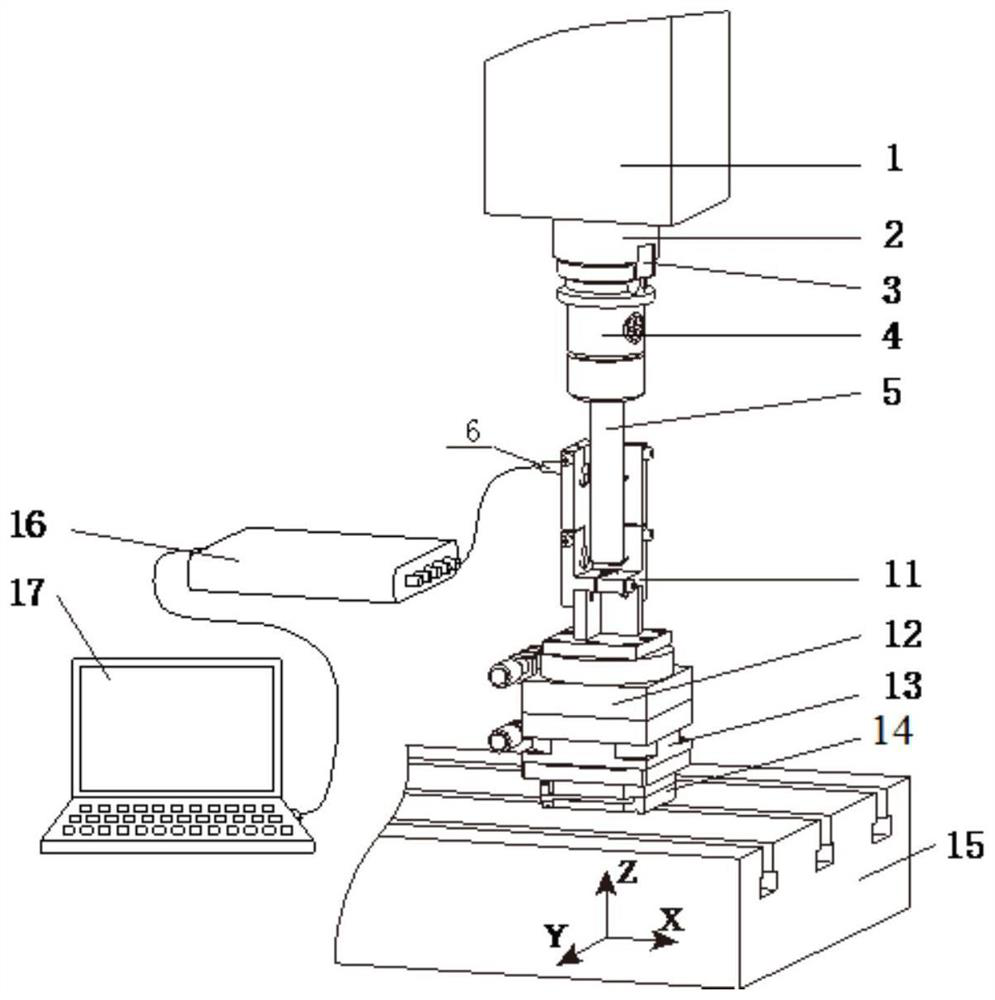
[0036] Existing CNC machine tools are generally as figure 1 As shown, it mainly includes a spindle box 1, a spindle 2, a spindle end face positioning key 3, a tool handle 4 and a machine tool table 15. The measuring device includes a mandrel 5, a non-contact displacement sensor 6, a sensor bracket 11, a three-axis precision adjustment platform 12, a connecting plate 13, an adjustable magnetic b...


PUM


Abstract

The invention belongs to the related technical field of precision measurement technology, and discloses a method for separating a core shaft roundness error in a numerical control machine tool spindle rotation error, and the method comprises the steps: carrying out the singularity analysis of the measurement error motion of a sensor through employing a wavelet transformation modulus maximum value and a Lee's exponent; according to the method, a main shaft accurate stop stage and each rotation period are accurately positioned from measurement error motion, and a WTMM ridge line extraction method is provided to extract continuous WTMM ridge lines, so that synchronous error motion is calculated from main shaft stable rotation stage signals intercepted from the WTMM ridge lines, signal segments meeting the preconditions of a reverse method are intercepted from the synchronous error motion, and the main shaft accurate stop stage and each rotation period are calculated. Finally, separation of core shaft roundness error motion and main shaft error motion is achieved through a reverse method. The invention provides a mandrel roundness error separation method which is more accurate and convenient and can be suitable for numerical control machine tool spindle rotation error on-machine measurement.

Description

technical field [0001] The invention belongs to the technical field related to precision measurement technology, and more specifically relates to a method for separating the roundness error of the spindle from the rotation error of the spindle of a numerically controlled machine tool. Background technique [0002] The spindle unit is the core component of the metal cutting machine tool to directly clamp the tool to perform cutting. The rotation error of the spindle will have a serious impact on the dimensional accuracy, shape and position error and surface roughness of the machined parts. Therefore, the accurate measurement of the rotation error of the machine tool spindle is The important supporting technology to improve the manufacturing level of machine tools and spindles is also an important means to timely and accurately grasp the health status and processing capabilities of machine tool equipment. [0003] At present, the method of using non-contact sensors to measure ...

Claims


Application Information

Patent Timeline
IPC IPC(8): G06K9/00
CPCG06F2218/06G06F2218/08G06F2218/12
Inventor 杨建中孔刚
Owner HUAZHONG UNIV OF SCI & TECH
Why Eureka
Try Eureka