Cascade circuit and control method thereof

A technology of cascading circuits and circuits, which is applied in the direction of control/regulation systems, electrical components, and adjustment of electrical variables, etc., can solve the problems of transformer conduction loss increase and peak voltage stress, etc., to achieve reduced conduction loss and EMI improvement , the effect of volume reduction

Pending Publication Date: 2022-03-22
MORNSUN GUANGZHOU SCI & TECH
View PDF6 Cites 1 Cited by
  • Summary
  • Abstract
  • Description
  • Claims
  • Application Information

AI Technical Summary

Problems solved by technology

In addition, in the current feed chapter of the book "Switching Power Supply Design" published in 1998, the Buck+ push-pull circuit and control are mentioned, which is the same as image 3 and Figure 4 similar, please refer to Figure 5 , although compared to figure 2 The switch tube Q3, switch tube Q4 and capacitor C1 are omitted, but when the current in the inductor L is inconsistent with the leakage inductance current of the transformer T, the peak voltage generated by Vbus superimposes the energy of the transformer leakage inductance to make the peak voltage of the switch tubes Q5 and Q6 The stress is very large, and the switching tubes Q5 and Q6 are turned on at the same time, and the current to excite the inductor L must pass through the primary winding of the transformer T, which increases the conduction loss of the primary side of the transformer.

Method used


Image

  • Cascade circuit and control method thereof
  • Cascade circuit and control method thereof
  • Cascade circuit and control method thereof

Examples


no. 1 example

[0049] Please refer to Figure 7 , Figure 7 It is a schematic diagram of the rear-stage isolated switching power supply circuit in the first embodiment of the cascade circuit of the present invention, including a primary side switch circuit, a transformer T1 and a secondary side rectifier circuit; the primary side switch circuit includes two switch tubes, and the two switch tubes are connected to The transformer forms a push-pull circuit; the secondary side rectification circuit includes two switch tubes, and the two switch tubes and the transformer form a full-wave rectification circuit; details are as follows:

[0050] The primary switch circuit includes a switch tube Q101 and a switch tube Q102;

[0051] The transformer T1 includes a primary winding with a center tap and a secondary winding with a center tap;

[0052] The secondary side rectification circuit includes a switching tube Q201 and a switching tube Q202;

[0053] One end of the switching tube Q101 is connecte...

no. 2 example

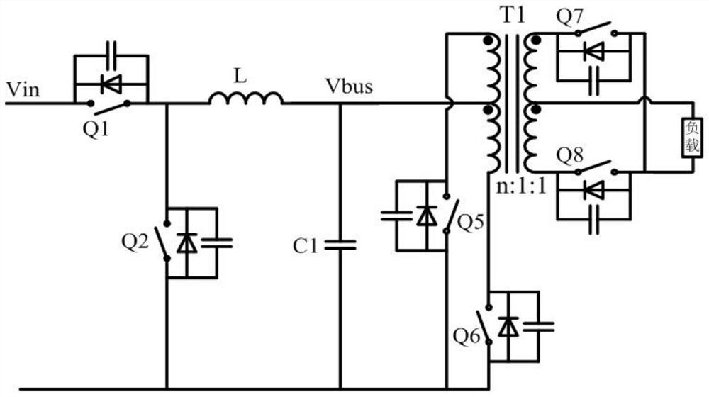
[0057] Please refer to Figure 8 , Figure 8 It is a schematic diagram of the rear-stage isolated switching power supply circuit in the second embodiment of the cascade circuit of the present invention, including a primary side switch circuit, a transformer T1 and a secondary side rectifier circuit; the primary side switch circuit includes four switch tubes, and the four switch tubes and The transformer forms a full-bridge circuit; the secondary side rectifier circuit includes two switch tubes, and the two switch tubes and the transformer form a full-wave rectifier circuit; details are as follows:

[0058] The primary switch circuit includes a switch tube Q111, a switch tube Q112, a switch tube Q113 and a switch tube Q114;

[0059] Transformer T1 includes a primary winding and a secondary winding with a center tap;

[0060] The secondary side rectification circuit includes a switching tube Q211 and a switching tube Q212;

[0061] One end of the switch tube Q111 and one end ...

no. 3 example

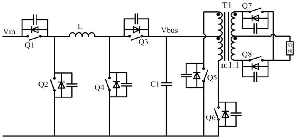
[0065] Please refer to Figure 9 , Figure 9 It is a schematic diagram of the rear-stage isolated switching power supply circuit in the third embodiment of the cascade circuit of the present invention, including a primary side switch circuit, a transformer T1 and a secondary side rectifier circuit; the primary side switch circuit includes four switch tubes, and the four switch tubes and The transformer forms a full-bridge circuit; the secondary side rectifier circuit includes four switch tubes, and the four switch tubes and the transformer form a full-bridge rectifier circuit; details are as follows:

[0066] The primary switch circuit includes a switch tube Q121, a switch tube Q122, a switch tube Q123 and a switch tube Q124;

[0067] Transformer T1 includes a primary winding and a secondary winding;

[0068] The secondary side rectification circuit includes switch tube Q221, switch tube Q222, switch tube Q223 and switch tube Q224;

[0069]One end of the switch tube Q121 an...


PUM


Abstract

The invention discloses a cascade circuit and a control method thereof, the cascade circuit comprises a pre-stage buck-boost circuit and a post-stage isolation switch power supply circuit, the buck-boost circuit comprises switch tubes Q1 to Q4, an inductor L and a capacitor C1; one end of the switching tube Q1 serves as the positive input of the buck-boost circuit, the other end of the switching tube Q1 is connected with one end of the switching tube Q2 and one end of the inductor L, the other end of the inductor L, one end of the switching tube Q4 and one end of the capacitor C1 are connected together to serve as the positive output of the buck-boost circuit, and the other end of the capacitor C1 is connected with one end of the switching tube Q3. And the other end of the switching tube Q2, the other end of the switching tube Q4 and the other end of the switching tube Q3 are connected together to form an input power ground of the buck-boost circuit. According to the invention, the switching tube Q4 and the active clamping circuit formed by the switching tube Q3 and the capacitor C1 are combined with a buck-boost control method, so that the device type selection, EMI and efficiency of the switching tube are greatly optimized, and the cost and the size are reduced.

Description

technical field [0001] The invention relates to the field of switching power supplies, in particular to a cascaded circuit and a control method thereof. Background technique [0002] Please refer to figure 1 , which is a well-known Buck+push-pull two-stage cascade circuit. The bus capacitor C1 decouples the front-stage Buck and the rear-stage push-pull, and the working process basically does not affect each other. The output bus voltage of the front-stage Buck is in the form of a voltage source Stage push-pull power supply, forming a working mode of voltage feed, which is often used in wide input voltage scenarios. Compared with single-stage topologies such as flyback and forward, figure 1 The push-pull circuit in the middle and rear stages is completely decoupled from the change of the input voltage, the selection of the primary and secondary switch tubes and the design of the transformer become very simple, and at the same time, the power supply efficiency is improved, th...

Claims


Application Information

Patent Timeline
Patent Type & Authority Applications(China)
IPC IPC(8): H02M3/335H02M1/44
CPCH02M3/3353H02M1/44
Inventor 不公告发明人
Owner MORNSUN GUANGZHOU SCI & TECH
Why Eureka
Try Eureka