Vibration well cementation device with mechanical energy storage function and using method and testing device of vibration well cementation device
A technology of mechanical energy storage and energy storage device, which is applied to vibration generating devices, earth-moving drilling, wellbore/well components, etc., can solve the problems of complex cementing site construction and other problems, achieve simple design, improve compactness and uniformity , the effect of low cost
- Summary
- Abstract
- Description
- Claims
- Application Information
AI Technical Summary
Problems solved by technology
Method used
Image
Examples
Embodiment 1
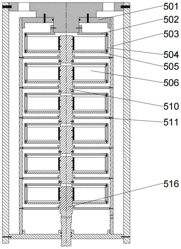
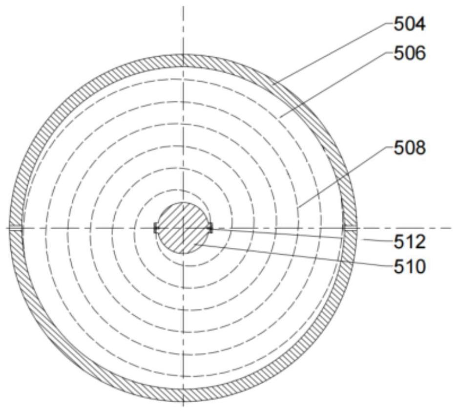
[0128] figure 1 It is a structural schematic diagram of a vibration cementing device with mechanical energy storage. The device includes: casing 1, rubber plug seat 2, energy release trigger device 3, upper support plate 4, energy storage device 5, ratchet pawl mechanism 6, lower support plate 7, eccentric block I8, eccentric block II16 and eccentric block III19, vibration support plate I9, vibration support plate II15, vibration support plate III18, shear pin shaft 10, short transmission shaft 11, transmission gear I12, transducer device 13, transmission gear II14, vibration shaft 17. The mechanical energy storage type downhole vibration cementing tool is lowered into the preset position in the oil and gas well. During the process of cement injection and cement slurry replacement, the energy conversion device 13 converts the kinetic energy of the fluid into the kinetic energy of the shaft on the one hand, and drives it through the transmission gear II14 on the other hand. Th...
Embodiment 2
[0138] Figure 6 Another structural form of a downhole vibratory cementing tool with mechanical energy storage is shown, the difference lies in the different structures of the energy discharge trigger device 3, the overload protection device and the energy conversion device. It mainly includes: casing 1, rubber plug seat 2, energy release trigger device 3, upper support plate 4, energy storage device 5, ratchet pawl mechanism 6, lower support plate 7, eccentric block 8, end vibration shaft 9, overload protection A device 10, a vibration support plate 11, a vibration shaft 12, and a transducer. Its principle and figure 1 The structure is the same as shown, and will not be described in detail here, only the energy-discharging trigger device, overload protection device and energy conversion device are supplemented.
[0139] Figure 7 The shown energy release trigger device 3 is mainly composed of a switch support frame 301 , an expansion material 302 in case of water and oil, ...
PUM
 Abstract
Description
Claims
Application Information
 - R&D
- Intellectual Property
- Life Sciences
- Materials
- Tech Scout
- Unparalleled Data Quality
- Higher Quality Content
- 60% Fewer Hallucinations
Browse by: Latest US Patents, China's latest patents, Technical Efficacy Thesaurus, Application Domain, Technology Topic, Popular Technical Reports.
© 2025 PatSnap. All rights reserved.Legal|Privacy policy|Modern Slavery Act Transparency Statement|Sitemap|About US| Contact US: help@patsnap.com


