Sapphire optical fiber F-P cavity cascade SFBG high-temperature strain sensor

A high-temperature strain, sapphire technology, applied in instruments, optical devices, measuring devices, etc., can solve problems such as demodulation accuracy and system stability deterioration, the influence of the reflected wavelength of optical fiber sensors, and crosstalk between temperature signals and strain signals. Reduced end-face reflections, easy processing and demodulation, high-precision effects

Active Publication Date: 2022-04-05
NAT UNIV OF DEFENSE TECH
View PDF7 Cites 0 Cited by
  • Summary
  • Abstract
  • Description
  • Claims
  • Application Information

AI Technical Summary

Problems solved by technology

[0003] The most widely used in current engineering is the resistance strain sensor, but the resistance strain sensor has the following technical defects in the high temperature strain test: First, the insulation resistance value drops, and high temperature or humid environment will cause a large drop in the insulation resistance value, which will cause performance unstable
The second is zero drift, which is especially serious under harsh conditions
Third, the application range of high temperature is limited, and it is difficult to meet the high temperature strain test above 1500 °C
However, both temperature and strain will affect the reflection wavelength of the fiber optic sensor, resulting in the crosstalk between the temperature signal and the strain signal. So far, the problem of cross sensitivity of the fiber optic high temperature strain sensor has not been well solved.
In addition, sapphire fiber is an unclad multimode fiber. Compared with single-mode fiber, multimode interference will cause a decrease in the signal-to-noise ratio of the system, which in turn will lead to poorer demodulation accuracy and system stability.

Method used


Image

  • Sapphire optical fiber F-P cavity cascade SFBG high-temperature strain sensor
  • Sapphire optical fiber F-P cavity cascade SFBG high-temperature strain sensor
  • Sapphire optical fiber F-P cavity cascade SFBG high-temperature strain sensor

Examples


Embodiment Construction

[0062] The following will clearly and completely describe the technical solutions in the embodiments of the present invention with reference to the accompanying drawings in the embodiments of the present invention. Obviously, the described embodiments are only some, not all, embodiments of the present invention. Based on the embodiments of the present invention, all other embodiments obtained by persons of ordinary skill in the art without making creative efforts belong to the protection scope of the present invention.

[0063] In order to make the above objects, features and advantages of the present invention more comprehensible, the present invention will be further described in detail below in conjunction with the accompanying drawings and specific embodiments.

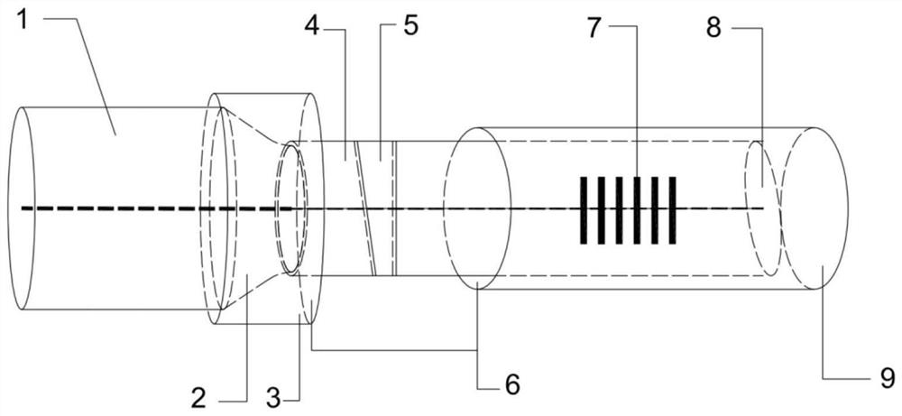
[0064] figure 1 It is a schematic diagram of a high-temperature strain sensor of a sapphire fiber F-P cavity cascaded SFBG according to an embodiment of the present invention.

[0065] Such as figure 1 As shown,...


PUM

PropertyMeasurementUnit
diameteraaaaaaaaaa
lengthaaaaaaaaaa
lengthaaaaaaaaaa

Abstract

The invention discloses a sapphire optical fiber F-P cavity cascade SFBG high-temperature strain sensor which comprises a gold-plated high-temperature-resistant single-mode optical fiber, one end of the gold-plated high-temperature-resistant single-mode optical fiber is provided with a single-mode optical fiber conical area, and the gold-plated high-temperature-resistant single-mode optical fiber is connected with a sapphire optical fiber through the single-mode optical fiber conical area. The end face, away from the gold-plated high-temperature-resistant single-mode fiber, of the sapphire fiber is a dip angle reflecting face. A trapezoidal air F-P cavity is formed in the sapphire optical fiber, a sapphire optical fiber Bragg grating is arranged in the sapphire optical fiber, and the trapezoidal air F-P cavity is located between the single-mode optical fiber conical area and the sapphire optical fiber Bragg grating; a stainless steel tube fixedly sleeves the outer side of the single-mode optical fiber conical area, an alundum tube fixedly sleeves the outer side of the sapphire optical fiber, and the alundum tube and the sapphire optical fiber Bragg grating are correspondingly arranged. According to the invention, a large-range measurement effect of a temperature range from room temperature to 1800 DEG C and a strain range of 0-1500 [mu] epsilon can be achieved, and the sensor is high in measurement sensitivity and high in precision.

Description

technical field [0001] The invention relates to the technical field of optical fiber sensing, in particular to a high temperature strain sensor of sapphire optical fiber F-P cavity cascaded SFBG. Background technique [0002] In the fields of aerospace vehicles, engines, metallurgy, chemical industry, machinery manufacturing and other fields, the demand for strain measurement under high temperature conditions has become more and more urgent in recent years. Taking the health monitoring of aerospace and aero engines as an example, the temperature in the combustion chamber of a rocket engine is as high as 1700°C, and the pressure pulsation generated in the combustion chamber of the engine will cause combustion instability, which will lead to a decrease in engine performance and increase the probability of accidents. Therefore, it is of great significance to monitor the internal strain parameters of the engine combustion chamber under high temperature conditions. An ideal high...

Claims


Application Information

Patent Timeline
Patent Type & Authority Applications(China)
IPC IPC(8): G01B11/16
Inventor 于洋梁建桥朱宏田卞强朱家健陈勇路阳
Owner NAT UNIV OF DEFENSE TECH
Why Eureka
Try Eureka