Millimeter wave wide-frequency-band high-gain dual-polarization magnetoelectric dipole filtering antenna

A filter antenna, high gain technology, applied in the field of radio frequency communication, can solve the problems of increasing the number of dielectric plates, increasing the size of the antenna, complex feeding network, etc., to achieve the effect of enhanced filtering performance, simple structure and high gain

Active Publication Date: 2022-04-05
XIAMEN UNIV
View PDF19 Cites 6 Cited by
  • Summary
  • Abstract
  • Description
  • Claims
  • Application Information

AI Technical Summary

Problems solved by technology

This solution usually requires multiple resonators connected in series, which not only increases the size of the antenna, but also introduces the insertion loss of the filter network, which is not conducive to the application of 5G millimeter wave systems
The second method is to add additional structures such as slots, parasitic patches or short-circuit probes to the radiation part of the antenna. This method does not introduce insertion loss in the operating frequency band, but the structure of the antenna is very complex.
However, when the frequency enters the millimeter-wave frequency band, if the uneven L-shaped probe is used, it means that the two feeding parts need to be printed on the dielectric board at different heights, which leads to an increase in the number of layers of the dielectric board, processing costs and design complexity. Becomes high
[0005]In addition, for high-gain antenna design, the traditional method is to use antenna arrays. However, if the number of antenna elements is large and the antenna is dual-polarized, the feed network It will be more complicated, and the insertion loss in the mmWave frequency band has a great influence

Method used


Image

  • Millimeter wave wide-frequency-band high-gain dual-polarization magnetoelectric dipole filtering antenna
  • Millimeter wave wide-frequency-band high-gain dual-polarization magnetoelectric dipole filtering antenna
  • Millimeter wave wide-frequency-band high-gain dual-polarization magnetoelectric dipole filtering antenna

Examples


Embodiment Construction

[0039] The present invention will be further described in connection with the embodiments and the drawings, but the embodiments of the present invention are not limited thereto.

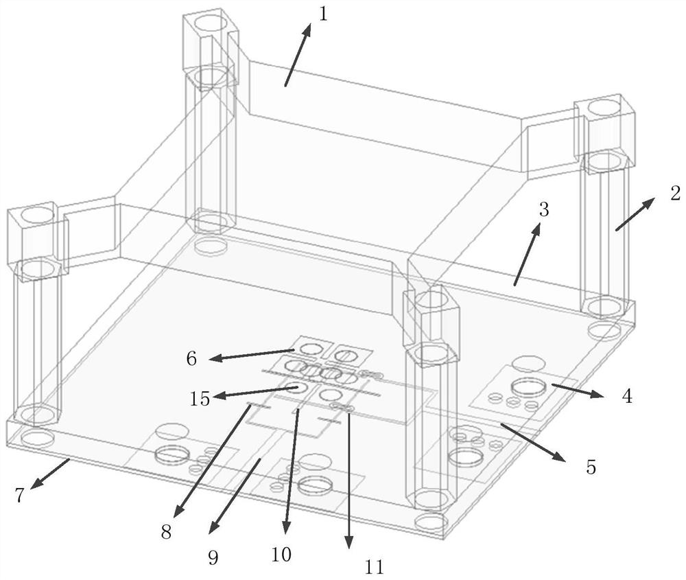
[0040] A high gain bipolar broadband magnetic electrobular filter antenna applied to a 5G mm wave system, including a top dielectric substrate, an intermediate layer dielectric substrate, and a bottom dielectric substrate, and the upper and lower surface of the top dielectric substrate is not printing metal. The upper surface printed radiator structure of the intermediate layer dielectric substrate, the bottom dielectric substrate printing slit coupled feed network structure;

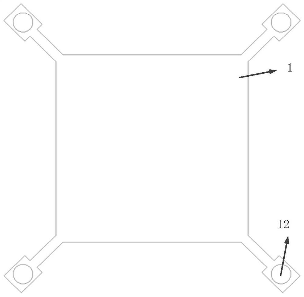
[0041] The top dielectric substrate is a high dielectric constant dielectric plate that functions as a focus beam;

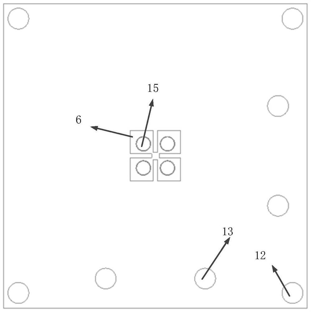
[0042] The radiator structure includes four symmetrical and connected parasitic patchs, and the parasitic patch is loaded with metallized via;

[0043] The slit coupled feed network includes two sets of orthogonal p...


PUM


Abstract

The invention discloses a millimeter wave wide-frequency-band high-gain dual-polarization magnetoelectric dipole filtering antenna, and relates to the field of radio frequency communication. Comprising a top-layer dielectric substrate, a middle-layer dielectric substrate and a bottom-layer dielectric substrate, the top-layer dielectric substrate is a square dielectric substrate, a radiator structure is printed on the upper surface of the middle-layer dielectric substrate, and a gap coupling feed network structure is printed on the bottom-layer dielectric substrate; the radiator structure comprises four symmetrical and connected parasitic patches, metalized via holes are loaded on the parasitic patches, the slot coupling feed network comprises two groups of orthogonally arranged Y-shaped feed lines and four coupling rectangular slots, and the four rectangular coupling slots are loaded on the metal floor. Other filtering structures are not introduced, a low-frequency radiation zero point can be controlled by changing the length of the electric dipole and the height of the magnetic dipole, a high-frequency zero point is generated by prolonging the length of the feeder line under the coupling gap, and a new higher-frequency zero point is introduced by changing the length of the coupling gap, so that the high-frequency out-of-band filtering performance is improved.

Description

Technical field [0001] The present invention relates to the field of radio frequency communications, and in particular to a high gain bipolar magnetocouple positive filter antenna applied to a 5 g millimeter wave system. Background technique [0002] 5G millimeter wave technology is an important technique in 5G applications. The millimeter wave refers to electromagnetic waves from 1 mm to 10mm. The millimeter wave has unique advantages such as large bandwidth, low-cost delay and flexible elasticity, and can meet future wireless communications. Demand for system capacity, transmission rate, and differentiation applications. [0003] Filter antenna is a emerging technique that combines antenna and filtering function. Filter antenna has the advantages of high efficiency, small insertion loss, is expected to be applied in modern wireless communication systems. In recent years, there are two conventional methods of realizing filtering antennas, one is to link antenna and filter level,...

Claims


Application Information

Patent Timeline
Patent Type & Authority Applications(China)
IPC IPC(8): H01Q9/04H01Q9/16H01Q5/20H01Q5/50H01Q1/00H01Q1/24H01Q1/52
Inventor 张垚黄楷
Owner XIAMEN UNIV
Why Eureka
Try Eureka