Flue gas, oil gas and dust separation and recycling system of asphalt mixing station

An asphalt mixing, separation and recovery technology, applied in separation methods, solid separation, dispersed particle separation, etc., can solve problems such as environmental pollution, and achieve the effects of reducing environmental pollution, rational design, and increasing contact area.

Active Publication Date: 2022-04-12
HEFEI UNIV OF TECH
View PDF5 Cites 1 Cited by
  • Summary
  • Abstract
  • Description
  • Claims
  • Application Information

AI Technical Summary

Problems solved by technology

[0004] The purpose of the present invention is to provide a smoke oil gas dust separation recovery and reuse system in an asphalt mixing plant to solve the problems caused by mixing asphalt and aggregate in the mixing bin The flue gas dust is directly discharged into the atmosphere, causing environmental pollution, and the problem of using smoke oil gas dust has not been effectively dealt with

Method used


Image

  • Flue gas, oil gas and dust separation and recycling system of asphalt mixing station
  • Flue gas, oil gas and dust separation and recycling system of asphalt mixing station
  • Flue gas, oil gas and dust separation and recycling system of asphalt mixing station

Examples


Embodiment 1

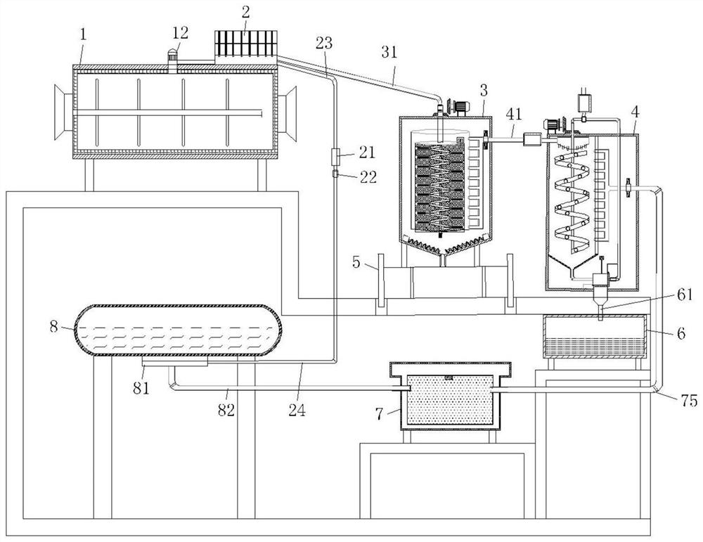
[0026] refer to figure 1 , a smoke oil gas dust separation recovery and reuse system of an asphalt mixing station, including a working box, a mixing bin 1 is installed on one side of the top surface of the working box body, and an electrical appliance is installed on the top side of the mixing bin 1 The tar catcher 2, a suction pump 12 is connected between the smoke outlet at the top of the mixing bin 1 and the input end of the electric tar catcher 2, and the oil outlet of the electric tar catcher 2 is connected to an oil collection tank 21 through a pipeline, so An oil pump 22 is installed on the lower side of the oil collecting tank 21, an asphalt tank 8 is fixed on the bottom surface of the working box close to the mixing chamber 1, and a burner 81 is installed at the bottom of the asphalt tank 8, and the output end of the oil pump 22 passes through a pipeline Connected to the oil supply end of the burner 81, the collected tar is collected in the asphalt tank burner for hea...

Embodiment 2

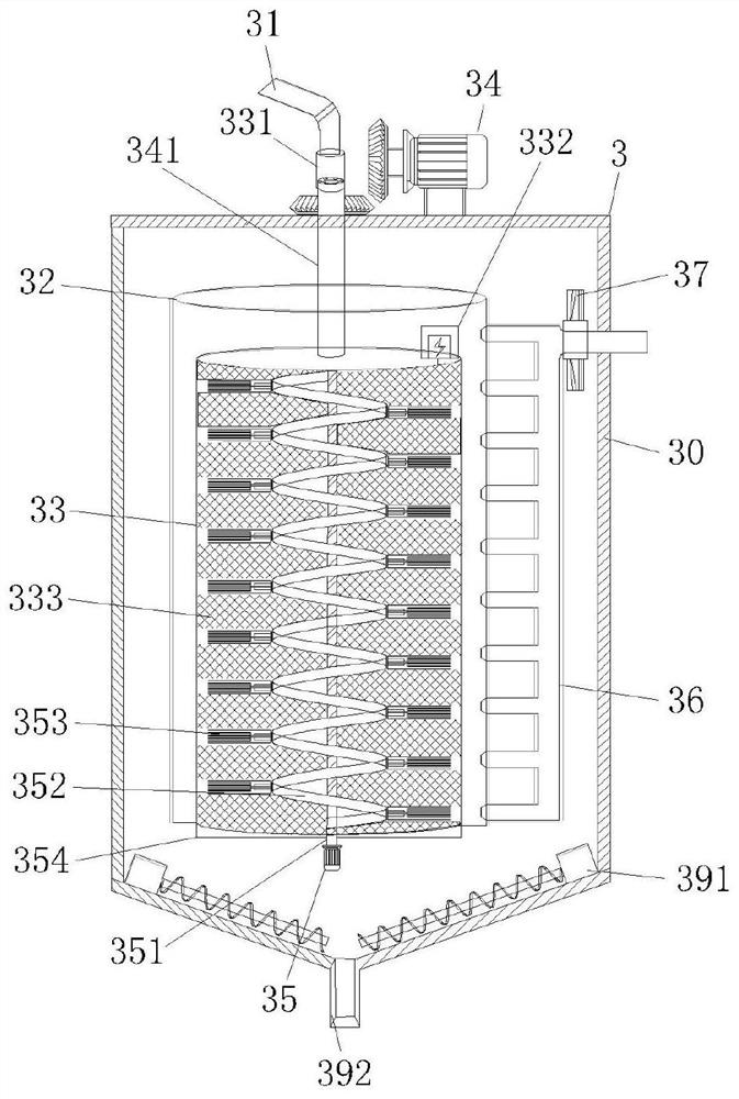
[0029] Such as figure 1 , 2 , 4 and 5, the present embodiment is basically the same as Embodiment 1. The dust screening mechanism 3 includes a screening cylinder body 30, and a large cylindrical barrel 32 and a small cylindrical barrel 32 are nested inside the screening cylinder body 30. Bucket 33, a drive motor I34 is installed in the middle of the outer top surface of the screening cylinder body 30, and a hollow rotating shaft 341 is fixed through the middle of the top of the small cylindrical barrel 33, and one end of the hollow rotating shaft 341 passes through the drive motor I34. The bevel gear set is rotationally connected, and the top end of the hollow rotating shaft 341 is connected to the dust guide pipe 31 through the rotary joint I331. A power supply assembly 332 is installed, a filter screen 333 is fixed on the side of the small cylindrical bucket 33, and a door 354 capable of opening and closing is installed at the bottom, the output end of the power supply asse...

Embodiment 3

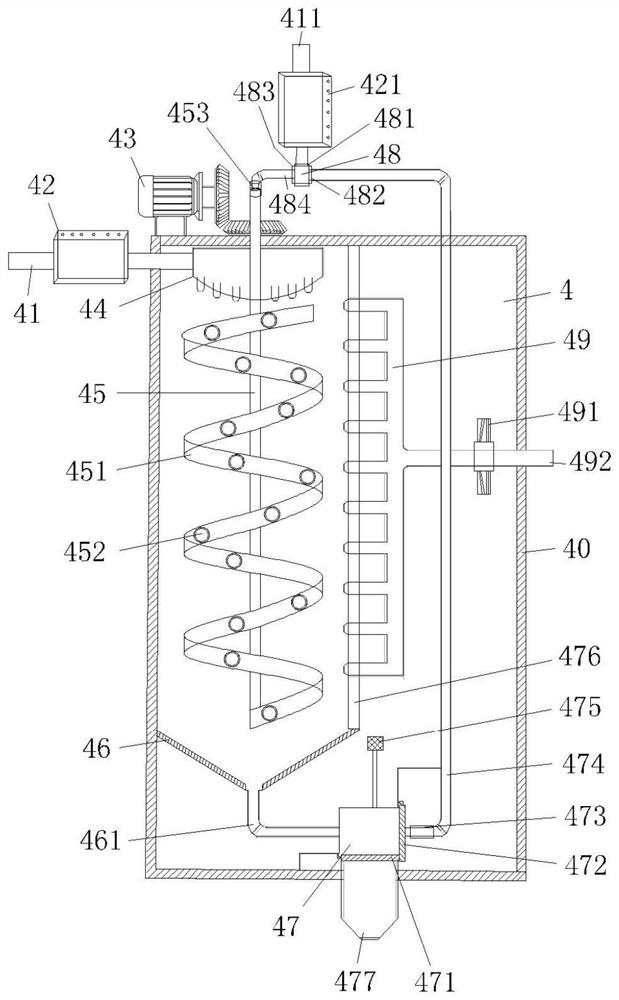
[0034] Such as figure 1 with 3 As shown, this embodiment is basically the same as Embodiment 1. Preferably, the circulating spray mechanism 4 includes a spray tank 40, a hollow shaft 45 runs through the top of the spray tank 40, and one side of the outer top surface of the spray tank 40 is fixed. There is a driving motor III 43, the output end of the driving motor III 43 is rotationally connected with the hollow shaft 45 through a bevel gear set, the hollow shaft 45 is sleeved on the outside and connected through a spiral conduit 451, and the top of the hollow shaft 45 is fixed with a rotary joint II 453, A water pipe 484 is fixed at one end of the swivel joint II 453, and a three-way valve 48 is installed on the water pipe 484. An electromagnetic flow valve I421 is connected to the upper side of the three-way valve 48, and one end of the electromagnetic flow valve I421 is connected to a water source 411. A gas flow divider 44 is provided, the inlet end of the gas flow divide...


PUM


Abstract

The invention discloses a smoke oil-gas-dust separation recycling system of an asphalt mixing station, which comprises a working box body, a mixing bin is mounted on one side of the outer top surface of the working box body, an electrical tar precipitator is mounted on one side of the top surface of the mixing bin, and a getter pump is connected between a smoke outlet at the top end of the mixing bin and the input end of the electrical tar precipitator; an oil collecting tank is connected to an oil outlet of the electrical tar precipitator through a pipeline, an oil pump is installed on the lower side of the oil collecting tank, an asphalt tank is fixed to the side, close to the mixing bin, of the inner bottom face of the working box body, a combustor is installed at the bottom end of the asphalt tank, a gas gathering pipe II is arranged on one side of the spiral guide pipe, and an induced draft fan II is arranged at one end of the gas gathering pipe II. The device is reasonable in design, a large amount of smoke, oil, gas and dust generated by stirring hot asphalt and various aggregates in the mixing bin of the asphalt mixing station can be effectively separated, and separated substances can be recycled.

Description

technical field [0001] The invention belongs to the field of tail gas treatment of an asphalt mixing plant, in particular the invention discloses a smoke oil gas dust separation recovery and reuse system of an asphalt mixing plant. Background technique [0002] The mixing bin of the asphalt mixing plant will produce a lot of smoke oil, gas and dust due to mixing hot asphalt and aggregate during operation. The mixing bin of the existing mixing plant is usually not closed, and the smoke oil gas produced by it will Dust will be discharged into the air. Because asphalt contains high boiling point mineral oil and a small amount of carbon and sulfur compounds, at high temperature, it may be oxidized and decomposed to produce toxic gases such as carbon monoxide, hydrogen sulfide and sulfur dioxide, causing pollution and harm to the environment. people in good health. [0003] At present, the method of separating dust in asphalt mixing plants will directly pass the dusty gas to the...

Claims


Application Information

Patent Timeline
IPC IPC(8): B01D53/78B01D46/24B01D46/681B01F27/70B03C3/017
Inventor 刘凯汪师培孙艺涵唐宁童健航黄沐阳徐晓倩赵俊仁丁伟伦
Owner HEFEI UNIV OF TECH
Why Eureka
Try Eureka