Phase change heat storage curing device for concrete structure in cold environment and implementation method of phase change heat storage curing device

A concrete structure and phase change heat storage technology, applied in the field of civil engineering, can solve problems such as time and space differences in solar energy resources, difficulty in judging the energy requirements of phase change materials for solar energy resources, and uneven distribution of solar energy in time and space, so as to reduce carbon Emissions and the effect of reducing energy consumption

Active Publication Date: 2022-04-12
HEBEI UNIV OF TECH
View PDF7 Cites 0 Cited by
  • Summary
  • Abstract
  • Description
  • Claims
  • Application Information

AI Technical Summary

Problems solved by technology

However, solar resources vary greatly in time and space
Phase change materials can store a large amount of energy through the transition of phase state, and the use of phase change materials for solar energy storage can overcome the uneven distribution of solar energy in time; however, due to the differences in solar energy resources in different regions, it is difficult to judge the solar energy resources in this region with existing methods Whether it meets the energy requirements of the phase change of the phase change material, and there are few methods to guide how to design the phase change material according to the solar energy resources in the corresponding area, so as to maximize the utilization of the phase change material in the local solar environment
[0004] Therefore, the present invention provides a phase-change heat storage maintenance device for concrete structures in cold environments and its implementation method. The concrete is cured by using sunlight and heat, and the phase-change materials are designed for different solar-light-thermal conditions, which solves the problem of solar time and space. In the case of uneven distribution, it provides a set of solutions suitable for solar energy in different regions for photothermal phase change conservation

Method used


Image

  • Phase change heat storage curing device for concrete structure in cold environment and implementation method of phase change heat storage curing device
  • Phase change heat storage curing device for concrete structure in cold environment and implementation method of phase change heat storage curing device
  • Phase change heat storage curing device for concrete structure in cold environment and implementation method of phase change heat storage curing device

Examples


Embodiment 1

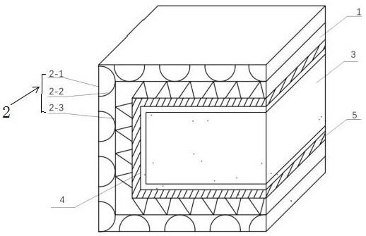
[0066] Example 1: Combining figure 1 To illustrate this embodiment, the one-way light-transmitting thermal insulation layer 2 in this embodiment is a multi-layer structure, and airbags are formed between each layer of the multi-layer structure to achieve a thermal insulation effect. The one-way light-transmissive thermal insulation layer 2 is supported by the interlayer The structure 1 is covered on the concrete formwork 4 as a whole, and the energy storage layer 5 is closely attached to the sunny side of the concrete; the shady side of the concrete is directly insulated by the interlayer support structure 1 and the one-way light-transmitting insulation layer 2, and no storage layer is set on the shady side. The interlayer support structure directly falls on the concrete formwork; the interlayer support structure 1 is a lightweight plastic cage or wooden cage, which can support the one-way light-transmitting insulation layer, which can ensure the support of one-way light trans...

Embodiment 2

[0067] Embodiment 2: the present embodiment is the further limitation of embodiment 1, and the inner and outer surfaces of unidirectional light-transmitting thermal insulation layer 2 adopts light-transmitting plastic film, and the inboard of light-transmitting plastic film on outer surface is provided with magnetron sputtering film, magnetron sputtering The film protrudes toward the concrete side to form an airbag structure to concentrate light, and only allows sunlight to pass through in one direction. The thickness of the magnetron sputtering film on the shady side and the sunny side is different. For the magnetron sputtering film on the positive side, Its one-way light transmittance should be more than 70% to ensure that sunlight can pass through the one-way light-transmitting insulation layer 2, and the infrared reflectance of the magnetron sputtering film on the shade side should be above 60% to ensure one-way light transmission. The heat insulation effect of the light in...

Embodiment 3

[0069] Embodiment 3: The maintenance device in this embodiment includes a one-way light-transmitting thermal insulation layer 2, an interlayer support structure 1, and an energy storage layer 5. The three are stacked sequentially from the outside to the inside, and the three form an integrated flexible coil that can be rolled up. Structure, after coiling and connection, it can form a three-dimensional structure with a cavity inside. After coiling, a movable connection port is set for the unclosed position, such as unclosed by bonding, sticky connection, buckle connection, zipper or pin connection. The location should be sealed. Before sealing, the components to be maintained, such as equipment and concrete, can be placed in the cavity to realize the complete wrapping of the components to be maintained. During the placement process, it is necessary to ensure that there is an energy storage layer on the sunny side. After placement, the unsealed The position is closed, and the int...


PUM

PropertyMeasurementUnit
Thicknessaaaaaaaaaa
Phase transition pointaaaaaaaaaa
Latent heat of phase changeaaaaaaaaaa

Abstract

The phase-change heat-storage curing device for the concrete structure in the cold environment and the implementation method of the phase-change heat-storage curing device are suitable for curing concrete under the low-temperature environment of construction in autumn and winter and construction in alpine regions, and by means of the device, solar energy can be efficiently utilized for curing the concrete, heat preservation is conducted on equipment, and the service life of the equipment is prolonged. Therefore, normal development of concrete strength in a low-temperature environment is ensured, low-temperature damage of equipment is prevented, and normal promotion of a construction process in the low-temperature environment is facilitated. The maintenance method can effectively evaluate the effect and the like of the phase-change energy storage material in combination with regions, provides a selection standard for the types of phase-change materials required by construction in different regions, can also judge whether local photo-thermal conditions are suitable for the maintenance device or not, and provides a method for judging whether solar energy is enough for phase change of the phase-change energy storage material or not. The application and design problems of the phase-change material can be guided by proposing related formulas under the solar energy condition and the direct guidance of the phase-change material to obtain what effect under the solar energy condition.

Description

technical field [0001] The invention belongs to the technical field of civil engineering, and in particular relates to a phase change heat storage maintenance device for concrete structures in a cold environment and a realization method thereof. Background technique [0002] When construction is carried out in the alpine region or in winter, due to the low temperature environment, the hydration rate of the cement in the concrete decreases or even stops, resulting in the inability of the concrete strength to continue to increase. Especially when the temperature is below 0°C, the moisture in the concrete freezes, and the concrete is easy to Brittle cracking occurs, resulting in the phenomenon of "crisp". Therefore, in a low temperature environment, it is very important to take insulation and heating measures for concrete; at present, on-site heating mainly uses electric heating or fuel to heat up the site. However, these two methods consume a lot of energy. When using electri...

Claims


Application Information

Patent Timeline
IPC IPC(8): E04G9/10E04G21/24F24S60/10
CPCY02E10/40
Inventor 马国伟刘雨时王玲
Owner HEBEI UNIV OF TECH
Why Eureka
Try Eureka