
Optical assembly for radar and silicon optical chip

A silicon photonics chip and optical component technology, applied in radio wave measurement systems, instruments, etc., can solve problems such as crosstalk and stray light, achieve the effects of reducing power consumption and cost, improving signal-to-noise ratio, and reducing the need for light filtering

Pending Publication Date: 2022-04-12
HESAI TECH CO LTD
View PDF0 Cites 10 Cited by
  • Summary
  • Abstract
  • Description
  • Claims
  • Application Information

AI Technical Summary

Problems solved by technology

[0006] Embodiments of the present invention solve the problems of crosstalk and stray light caused by using a circulator as a beam splitting device in the prior art by using a silicon photonic chip including a polarizing beam splitter or an optical coupler

Method used


Image

  • Optical assembly for radar and silicon optical chip
  • Optical assembly for radar and silicon optical chip
  • Optical assembly for radar and silicon optical chip

Examples


Embodiment Construction

[0037] In the following, only some exemplary embodiments are briefly described. As those skilled in the art would realize, the described embodiments may be modified in various different ways, all without departing from the spirit or scope of the present invention. Accordingly, the drawings and descriptions are to be regarded as illustrative in nature and not restrictive.

[0038] In describing the present invention, it is to be understood that the terms "center", "longitudinal", "transverse", "length", "width", "thickness", "upper", "lower", "front", " Back", "Left", "Right", "Vertical", "Horizontal", "Top", "Bottom", "Inner", "Outer", "Clockwise", "Counterclockwise", etc. or The positional relationship is based on the orientation or positional relationship shown in the drawings, which is only for the convenience of describing the present invention and simplifying the description, rather than indicating or implying that the referred device or element must have a specific orie...


PUM

PropertyMeasurementUnit
reflectanceaaaaaaaaaa

Abstract

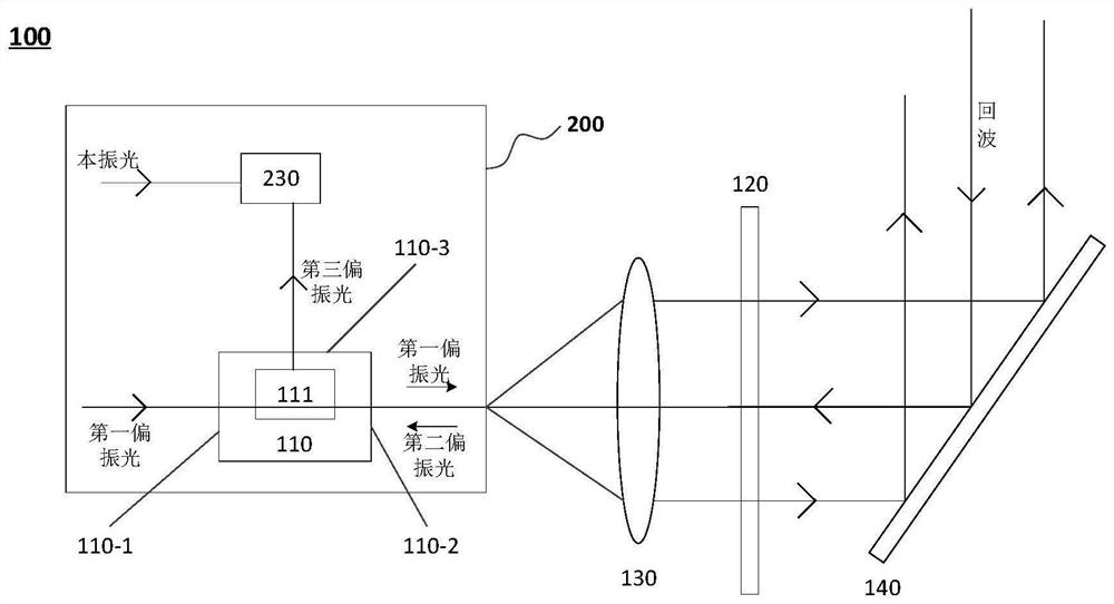
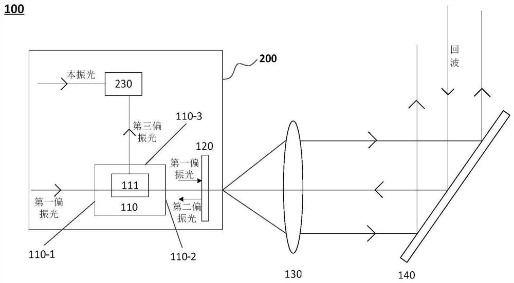
The present invention provides an optical assembly for radar, comprising: a polarization beam splitter configured such that a first port can receive first polarized light from a laser and output the first polarized light from a second port; the phase delay piece is configured to receive the first polarized light output by the second port from the polarization beam splitter, the first polarized light is emitted after passing through the phase delay piece, the phase delay piece is further configured to receive echoes of the radar, the echoes are adjusted into second polarized light after passing through the phase delay piece, and the second polarized light is emitted after passing through the polarization beam splitter. And the first polarized light enters the polarization beam splitter from the second port and is output from the third port, and the polarization direction of the first polarized light is perpendicular to the polarization direction of the second polarized light. According to the embodiment of the invention, crosstalk and stray light can be effectively reduced, the ranging precision of the radar is improved, and blind areas are reduced.

Description

technical field [0001] The present invention generally relates to the field of optoelectronic technology, and in particular to an optical component and a silicon optical chip that can be used for laser radar. Background technique [0002] Silicon photonics technology is a new generation technology based on silicon and silicon-based substrate materials (such as SiGe / Si, SOI, etc.), using existing CMOS technology for optical device development and integration, combined with the ultra-large-scale and ultra-high precision of integrated circuit technology The characteristics of manufacturing and the advantages of ultra-high speed and ultra-low power consumption of photonic technology. The silicon photonics architecture is mainly completed by silicon-based lasers, silicon-based optoelectronic integrated chips, active optical components and optical fiber packaging. Laser radar (LiDAR) requires multiple laser emission sources and receivers, or uses multi-channel signal control. The...

Claims


Application Information

Patent Timeline
Patent Type & Authority Applications(China)
IPC IPC(8): G01S7/481G01S7/484G01S7/487
Inventor 潘政清周南孙恺向少卿
Owner HESAI TECH CO LTD
Learn More